Led clear flex2 - rgb series – American Lighting CFX4V2-60-RGB User Manual
Page 2
LED Clear Flex2 - RGB Series
Installation intructions for CFX4V2-30-RGB and CFX4V2-60-RGB
INSTALLATION INSTRUCTIONS
1. Disconnect power at source before installation or maintenance.
2. Clear Flex2 requires DC 24V LED Power Supply! Do not connect to 120V AC power!
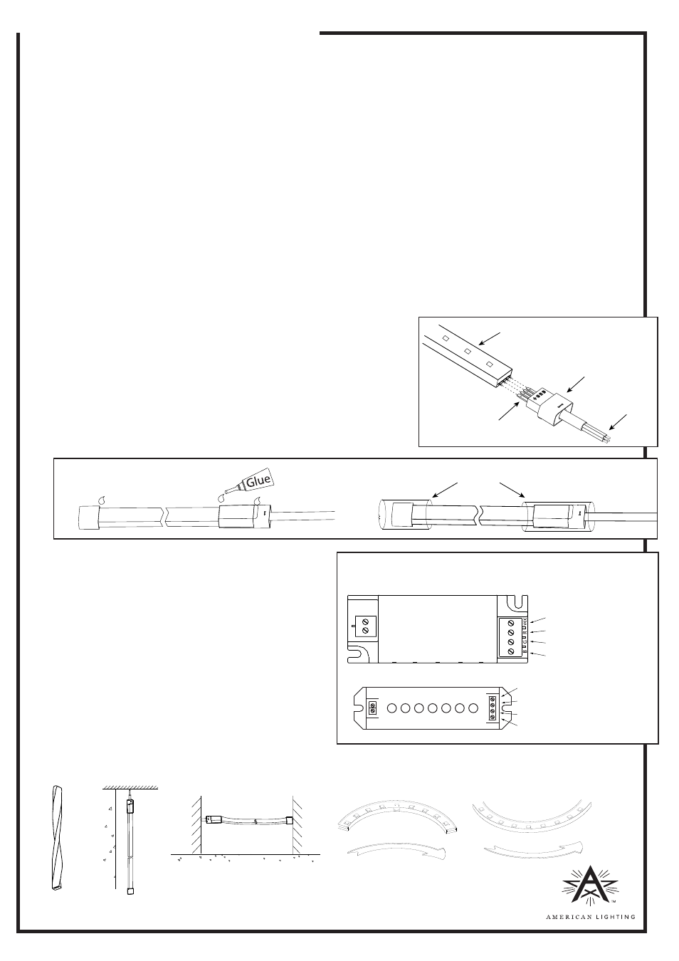
3. To connect power connection kit to the Clear Flex2:
• Push the pins of the connector kit into the end of the Clear Flex2 making sure that the four prongs make full
contact with the internal conductors. See Figure 1.
Note: Polarity is marked “ + R G B ” on the connector kit and Clear Flex2. If polarity is reversed, the LEDs will not be
damaged. They simply will not operate.
• Apply glue into the heat shrink tube, and slide the shrink tube over the joint where the power cord and Clear
Flex2 meet. See Figure 2.
• Use a heat gun to gently apply heat until the shrink tube shrinks in place over the assembly.
4. To connect the end cap to the Clear Flex2:
• Apply glue into the end cap and push the Clear Flex2 into the cap, until it is fully seated.
• Apply glue into the heat shrink tube and slide the shrink tube over the joint where the end cap and the Clear
Flex2 meet.
• Use a heat gun to gently apply heat until the shrink tube shrinks in place over the assembly.
5. To connect two sections of Clear Flex2 together using a splice connector:
• Slide the heat shrink tube onto one of the pieces of Clear Flex2 to be joined.
• Insert the connector pins into this piece of Clear Flex2 being sure to
make full contact with each of the internal conductors.
• Align the second piece of Clear Flex2 and push onto the connector
pins, making full contact with each internal conductor.
• Apply glue around the surface of both ends of the Clear Flex2
pieces and slide the heat shrink tube over the joint.
• Use a heat gun to gently apply heat until the shrink tube shrinks in
place over the assembly. Note: The glue must make contact with all
surfaces of the joints. Be sure that the heat shrink tube completely
covers each of the joints to maintain IP65 rating.
6. Clear Flex2 can be mounted using the mounting
clips (included with kit) or using aluminum
mounting channel (sold separately).
7. Clear Flex2 can be cut every six LEDs (approximately
every 3.9“ for CFX4V2-60-RGB or 7.8” for CFX4V2-30-
RGB). Cut squarely on the cutting mark. Cutting
anywhere else will result in loss of a whole section
(one series/parallel section = 6 LEDs).
8. Connect Clear Flex2 connector kit to controller,
ensuring the polarity is correct. See Figure 3.
9. Connect controller to 24V DC power supply matching
polarity (+ is positive, - is negative). Do not apply
120V AC power to Clear Flex2!
Please also refer to the power supply’s and IR or RF
wireless remote instructions.
DO NOT TWIST, HANG VERTICALLY, SUSPEND UNSUPPORTED IN THE MIDDLE OR BEND ALONG SHORT SIDE:
RV1317 www.americanlighting.com
Figure 1
Heat shrink tube
Figure 2
Figure 3
Ч
Ч
Ч
Ч
Ч
Connector pins
Lighted surface
Connector kit
Colored wires
(inside jacket)
Connect Yellow wire to VCC
Red wire to “R” terminal
Green wire to “G” terminal
Blue wire to “B” terminal
Connect colored wires from connector kit (shown
in Figure 1) to terminal matching polarity.
LED CONTROLLER
CFX4-144W-24V
connections
CFX4V2-360W-24V
connections
Connect Yellow wire to V
Blue wire to “B” terminal
Red wire to “R” terminal
Green wire to “G” terminal