American Lighting TL-60 Series User Manual
Page 2
LED FlexForm 30 & 60 - 12V Flexible Tape Light
Installation instructions for TL-30 and TL-60 Series
© American Lighting, Inc. 2012
www.americanlighting.com
RV-1247
CONNECTING AND MOUNTING FLEXFORM SECTIONS
This product is designed to be mounted to a smooth, non-moving surface.
1. Review any marks made indicating placement of connectors prior to continuing. For best adhesion to surface,
once FlexForm backing is removed, it should be placed on mounting surface and not be removed or repositioned.
2. Peel the protective backing from the adhesive tape and press the first piece of FlexForm into place. If there is an
“L” or “T”, this will be the first piece to be placed (then work back towards the piece where power attaches).
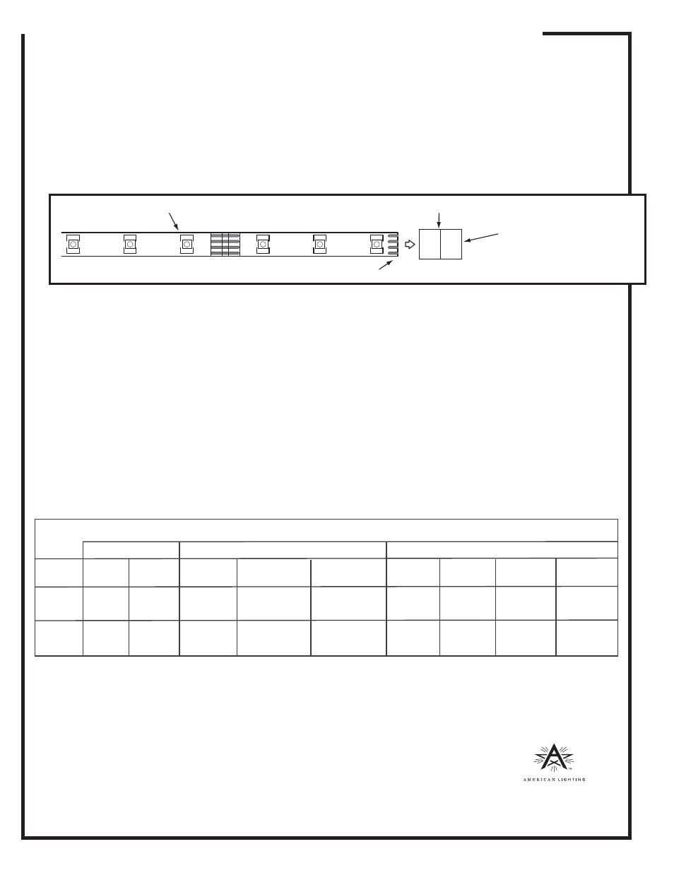
3. For extending any piece, connect inline connector supplied with the kit to the preceeding piece by inserting it
completely into the connector. See Figure 3. Additional inline connectors are sold separately, part number TL-SPL.
4. Attach the next FlexForm section to the inline connector in a similar manner.
5. For best results, allow 24 hours for the adhesive to “cure” to the mounting surface before using lights.
CONNECTING POWER
This LED product is designed to be used with a regulated 12V DC power supply only. Do not use a 12V AC transformer because
that will result in an “AC flicker” due to the alternating current output.
1. A power cord is pre-attached to each 16.4’ reel. Once a piece is cut from the reel, or for the 100’ reels, pieces will need a
power cord to be attached to a prepared end. Push the power cord fitting onto the prepared end of the FlexForm,
in a similar manner to the inline connector as illustrated above in Figure 3.
2. For plug-in installations, attach DC jack from white power cord to DC jack of plug-in power supply (part number
PS-36-12VPI (1-36 watts) or PS-60-12VPI (1-60 , each sold separately). Plug in power supply to 120V AC power source.
Item RCA-Y (sold separately) can be used as a splitter with plug-in power supplies.
3. For hardwire installations, use both the DC jack lead in conjunction with the mating DC to bare wire leads. The bare wire leads
will connect to the primary side of the power supply: either LED-DR-12 (1-25 watts), LED-DR60-12 (up to 60 watts) or
LED-DR100-12(up to 100 watts).
4. Attach the black power cord with DC jack to the white DC jack from step 1.
5. Attach bare leads of black power cord to leads (or terminals) of LED-DR driver, following LED-DR series instructions and
matching polarity (black lead wire on TL cord is negative, red lead wire is positive).
6. The non-powered end of the FlexForm does not require an end cap.
LED FlexForm
Inline Connector
The inline connector is easy
to connect to a prepared end
of the FlexForm. See reverse
side, Figure 1 or Figure 2, for
instructions about exposing
copper conductors.
Exposed copper conductors
Figure 3
ADDITIONAL SAFETY MEASURES:
1. Use only 3M® tape to secure FlexForm. For the availablility of track, please contact the factory.
2. Route and secure cords so that they will not be pinched or damaged in any way.
*Maximum run lengths shown are for a centrally located power supply with 2 or more EQUAL length runs that total the maximum load allowed.
Note: Plug-in power supplies are not dimmable. For dimming power supplies, see also PWM (Pulse Width Modulation) accessories within
“Power Supplies and Drivers” on www.americanlighting.com.
TL-60
4.4 W/ft
TL-30
2.2 W/ft
Item #
MAXIMUM FLEXFORM 30 & 60 RUNS CONNECTED TO ONE POWER SUPPLY
LED-DR-12 LED-DR60-12 LED-DR100-12
PS-25-12 PS-60-12 PS-100-12 PS-150-12
PLUG-IN TYPES
HARDWIRE (Non-dimming) TYPES
HARDWIRE (Dimming) TYPES
16.4’ 2* x 13.6’
11.4‘
2* x 13.6’
3* x 15.1’
11.4’
2* x 13.6’
3* x 15.1’
4* x 16.4’
8.2’
13.6’
5.7‘
13.6’
2* x 11.4’
5.7’
13.6’
2* x 11.4’
2* x 16.4’
PS-36-
12VPI
PS-60-
12VPI
Note: The National Electrical Code (NEC) does not permit cords to be concealed where damage
to insulation may go unnoticed. To prevent fire danger, do not run cord behind walls, ceilings,
soffits, or cabinets where it may be inaccessible for examination. Cords should be visually
examined periodically and immediately replaced when and damage is noted.