Led mini step lights – American Lighting 023-0001 User Manual
Page 2
WARNING: These products may present a possible shock
or fire hazard if improperly installed or attached in any
way. Products should be installed in accordance with the
owners manual, current electrical codes and/or the
current National Electric Code (NEC).
IMPORTANT
The following instructions are provided to assure safe
installation and operation of LED Mini Step Lights. Please
read carefully before connecting or installing this
product.
1. The LED Mini Step Lights are a safe low voltage lighting
system that are suitable for indoor and outdoor locations.
2. Do not mount or support the LED Mini Step Lights in a
manner that can cut the outer jacket or damage wire
insulation.
3. Always make sure power is disconnected from the LED
fixtures before cutting, mounting, attaching terminal
block, attaching end cap or modifying in any way.
4. Do not exceed the maximum capacity of the 350mA
DC power supply used for any series configuration.
SPECIFICATIONS
• 1 – 8 lights can be powered by one LED-DR10-350PI
• 1 – 9 lights can be powered by one LED-DR12-350
• 1 – 14 lights can be powered by one LED-DR18-350
• Two runs of 1 – 14 LED Mini Step Lights can be powered
by one LED-DR36-350HW
• Constant current LED driver (350mA DC) is required
• Series wiring configuration only (do not wire in parallel)
• Hole mount size: 1-1/2” (for recessed applications only)
• Fixture height: 1-5/8”
• Wattage per Step Light: 1.25
BEFORE YOU START
• Always make sure the LED Mini Step Light is
disconnected from the power source before wiring.
• Determine the number of LED lights your application will
require. There are multiple power connection configurations
and accessories that allow many installation options. See
reverse side prior to installation to determine the best
configuration for each installation. Remember, in any case,
do not exceed the capacity of the power supply used for
any single run.
FOR HARDWIRE INSTALLATIONS
1. Check that the male Molex connector of each LED Mini Step
Light is in operable condition. If in operable condition, insert
male Molex connector into an open female port of the power
connector.
2. When powering only one Step Light, it is necessary to insert an
end cap, LED-END-350, into any open ports to complete the
series wiring. When powering any number of LED MIni Step
Lights, every port of each power connector must be connected to
an end cap, another power connector or a light. The whole set
will not light if any port remains empty.
CONNECTING TO POWER SUPPLY
Use a 350mA power supply as recommended by the factory. Use
of any other power supply will void the warranty. Make sure the
power source is disconnected before making any
connections.
1. When connecting to LED-DR12-350 or LED-DR18-350 power
supplies, plug the molex connector directly into the molex port
on the secondary side of the power supply.
2. When using LED-DR36-350HW power supply, cut off the molex
connector of the last power connector in the series and wire to
the secondary side of the driver, matching polarity. Connect solid
red power connector lead to power supply lead marked positive.
Black/red striped power connector lead goes to negative supply
lead.
3. Connect 120V AC power to the primary side matching polarity
and turn on power.
MOUNTING LED MINI STEP LIGHT
1. Always make sure power is disconnected before modifying,
mounting or installing a series of LED Mini Step Lights.
2. Drill a 1-1/2” hole in mounting surface.
3. Open steel spring clips. Feed wire through hole.
4. Make sure that the wire is not in contact with sharp objects.
5. Push light into hole and slowly release spring clips.
6. Maximum wattage per series is dependent upon the capacity
of the power supply. Add the number of lights and respective
wattage to assure you do not exceed the maximum wattage.
LED MINI STEP LIGHTS
Installation instructions for 023-0001 (CONTINUED FROM OTHER SIDE)
RV-0904KB
www.americanlighting.com
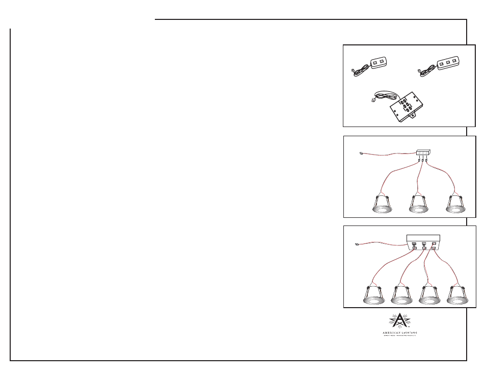
Figure 1
LED-CON2-350
LED-CON3-350
LED-CON6-350HW
Figure 2
Figure 3
LED-CON6-350
LED-CON3-350