Led linkworks – American Lighting LWX Series User Manual
Page 2
RV-1304
©2013 American Lighting
Denver, CO 80231 Made in China
www.americanlighting.com
WARNING: These products may represent a possible shock or fire hazard if improperly installed or attached in
any way. Products should be installed in accordance with these instructions, and with current electrical codes
and/or the current National Electric Code (NEC).
Warning: To avoid electric shock, disconnect power prior to installation.
Warning: This product is for use in horizontal installations only. Do not mount vertically! Failure to do so
will damage the fixture and may cause a fire hazard.
Save these instructions.
LED Linkworks
Installation Instructions for LWX Series
Installation:
(CONTINUED FROM REVERSE)
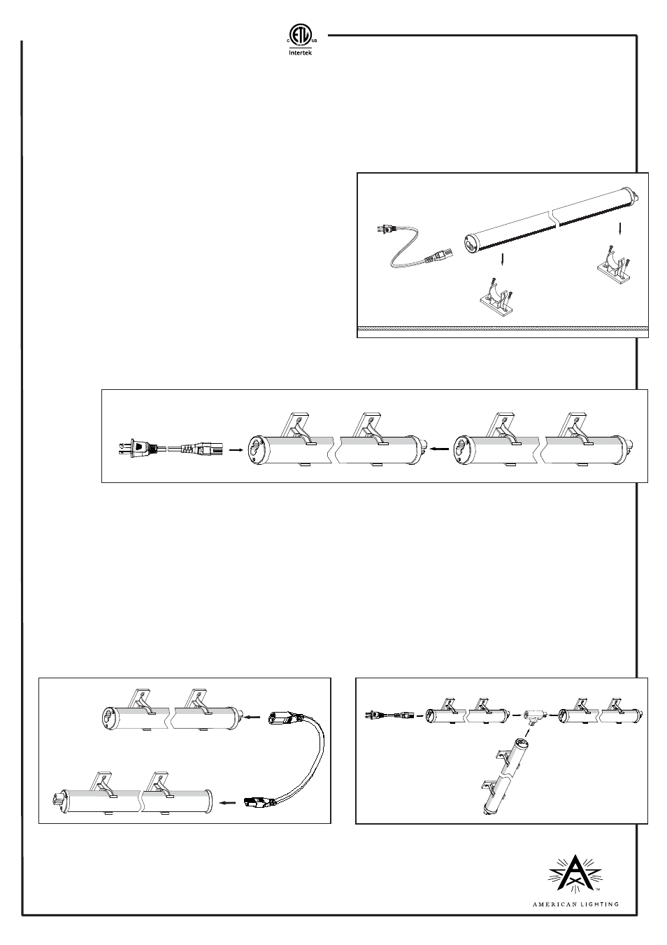
4. Snap first fixture into clips by pressing firmly with equal
pressure on the fixture body near clip locations.
See Figure 1. Attach power cord and make sure there
is room for its routing to a switched outlet, but DO NOT
plug into power outlet while installation is in progress.
Note: If switched outlet is not available, use switched
power cord (item number LWX-PC6-SW, sold separately).
5. Snap adjacent fixture into clips then slide horizontally
into first fixture and press them together firmly until
mating power connections are fully seated. See Figure 2.
6. Continue with subsequent fixtures in a like manner to complete installation.
7. Be sure to cap off the male end at the last fixture with end cap included with fixture.
Installation with linking extensions, Ts and Xs:
WARNING: Fixtures should NOT be installed or interconnected with power attached. Do not connect to power
while fixture is in the packaging. However, when installation is complete, check that all fixtures light up
properly when power is applied. If not, note any unlighted areas and disconnect power to correct the issue.
Most of the time, if a fixture or set of fixtures will not light, it is due to power connections not being firmly and
fully connected.
1. When using linking extensions, make sure that any straight line runs that were installed per the previous
section are able to mate. The male end of one series must be located within the linking extension’s reach of
the female end of the other series. See Figure 3.
2. When using Xs and/or Ts, connect straight line runs together that are are on opposite sides of the X or T per
the instructions in the previous section. Make sure to orient the ends properly to connect to the T or X. Slide
straight line runs into the connector until they are fully seated. Then do the other side(s) in a similar fashion.
See Figure 4.
3. Be sure to cap off any exposed male end(s) of all last fixtures with end cap included with fixture.
Figure 1
Figure 2
Figure 3
Figure 4
Male end
Female end
Male end
Female end
Cap off
male end.
Cap off
male end.
Cap off male end.
Cap off
male end.
Female end