12v xenon puck light – American Lighting ALPX Series User Manual
Page 2
CAUTION - To reduce risk of fire, electric shock or injury to persons:
1. This light is intended for use as a cabinet light only.
2. Not intended for installation in ceilings and soffits.
3. Not intended for lighting aquariums.
4. Lights are intended to point downwards only. Do not point upwards.
5. Not intended for installation in plastic cabinets. Mount only on wood
or particleboard surfaces that are mechanically sound.
6. Do not locate puck lights closer than 2” from a cabinet wall or in a
compartment smaller than 12” by 12” by 12” (one cubic foot) for each
light fixture. Three light fixtures require a minimum of three cubic
feet of enclosed space. Temperatures on the mounting surface can
reach 180˚F (82˚C).
7. Route and secure cords so they will not be pinched or damaged
when the cabinet is pushed to a wall.
8. Use only insulated cord retaining clips (included), staples or
plastic ties to secure cords.
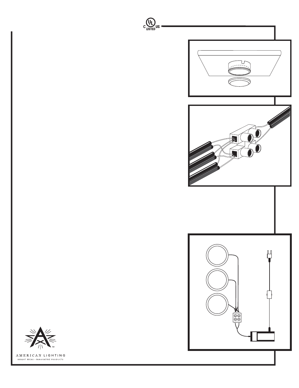
SURFACE MOUNTING (See Figure 1)
1. Remove lens cover by rotating counter-clockwise.
2. Mark desired position for the light. Be sure to orient notches for wires
in desired locations. Position puck light so as to permit reading of the
lamp replacement markings.
3. Drill ½” hole in mounting surface for wires to go through or use notch
in surface ring to route wires.
4. Mount housing to surface using the screws provided.
5. Replace lens cover.
6. Route wires through drilled hole or along surface to the terminal block of the transformer, attaching wires
with cord retaining clips and screws provided. Avoid contact of the cord or combustibles such as plastic,
paper goods, and the like, with the hot lamp housing or reflector.
7. Trim excess wire and strip ½” of insulation from end of wires.
8. For two or three Puck lights. (See Figures 2 and 3)
Take the ribbed wires from the puck lights and twist them together
into one connection. Repeat this process with the smooth wires.
9. Insert the ribbed wire cluster into the side of the terminal block that is
across from the ribbed wire coming from the transformer and screw
down the retaining screw to hold the wires in place. Insert the smooth
wires into the hole that is next to the ribbed wires and tighten screw.
10. Plug the transformer into a standard 120-volt outlet.
Lens Cover
Figure 1
Surface ring
and Housing
12V XENON PUCK LIGHT
Terminal Block
Figure 2
Puck
Terminal
Block
Transformer
Figure 3
Installation instructions for ALPX Series (ALPX20, ALPX40 & ALPX60 blister packs)
www.americanlighting.com
RV0906-KB