Interchangeable series led recessed downlight, Assembly diagram – American Lighting X34 Series User Manual
Page 2
Interchangeable Series LED Recessed Downlight
CAUTION: Always make sure power to the fixture is disconnected before beginning removal of
existing lamp and/or trim, or before beginning retrofit installation. Failure to do so can cause
electric shock, which can result in injury or death.
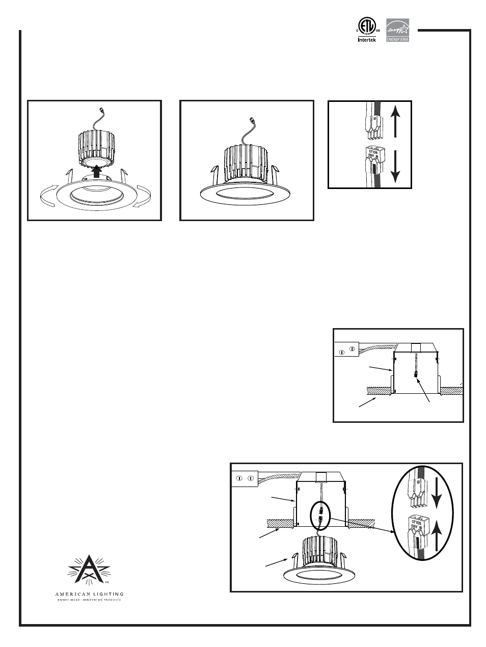
RETROFIT INSTALLATION
Figure 7
Recessed
housing
Ceiling
Ceiling
Figure 6
Insert male connector pins
into female connector and
press firmly until fully seated
NEW CONSTRUCTION INSTALLATION
Follow steps 1, then 4-7 above.
2013
Denver, CO 80231 • www.americanlighting.com
©
American Lighting, Inc.
RV1351 Page 2 of 3
E26, GU24 or GU10
socket adaptor
Spring
clips
Recessed
housing
Installation instructions for X34 Series (3”/4” adjustable retrofit)
ASSEMBLY DIAGRAM
Twist the baffle/multiplier into the trim piece. Push trim assembly up into light module and rotate baffle/multiplier
to the right until it stops (about 30-45 degrees clockwise) to lock trim assembly into place. See Figure 3.
When assembled the combined parts should look like Figure 4.
Figure 5
Light
module
Figure 3
Trim
Baffle/
multiplier
THE ASSEMBLED X34 DOWNLIGHT IS NOW READY FOR USE WITH A 3” or 4” RECESSED HOUSING.
Figure 4
1. Confirm the LED trim is compatible with the recessed housing as outlined on reverse.
2. Remove existing lamp from existing recessed housing.
3. Remove existing trim from existing recessed housing.
4. Detach E26 socket adaptor from LED fixture by grasping plastic connectors
firmly and pulling apart. Do not grasp wires to pull connectors apart.
See Figure 5.
5. Screw E26 socket adaptor into existing E26 socket at the back of the housing;
or push and twist GU24 (or GU10) socket adaptor into existing GU24 (or GU10)
socket at back of housing. See Figure 6.
6. Insert male connector pins into female connector and press firmly together
until fully seated. See Figure 7.
7. To install downlight/trim kit assembly: push fixture gently to ceiling letting spring clips hold the assembly in place.
See Figure 7. If needed, bend out the spring clips so they push
against the housing wall for added retention.