Interchangeable series led recessed downlight – American Lighting X56 Series User Manual
Page 2
Denver, CO 80231 • www.americanlighting.com
© 2013 American Lighting, Inc.
RV1321 Page 2 of 2
Interchangeable Series LED Recessed Downlight
2
1
CAUTION: Always make sure power to the fixture is disconnected before beginning removal of
existing lamp and/or trim, or before beginning retrofit installation. Failure to do so can cause
electric shock, which can result in injury or death.
RETROFIT INSTALLATION
1. Confirm the LED trim is compatible with the recessed housing as outlined on reverse.
2. Remove existing lamp from existing recessed housing.
3. Remove existing trim from existing recessed housing.
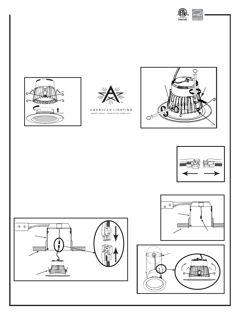
4. Detach E26 socket adaptor from LED fixture by grasping plastic connectors firmly
and pulling apart. Do not grasp wires to pull connectors apart. See Figure 4.
5. Screw E26 socket adaptor into existing E26 socket at the back of the housing; or push
and twist GU24 socket adaptor into existing GU24 socket at back of housing. See Figure 5.
6. Insert male connector pins into female connector and press firmly together
until fully seated. See Figure 6.
7. Insert trim torsion spring into corresponding retaining brackets in recessed
housing. Carefully push fixture gently to ceiling until seated. See Figure 7.
Figure 4
Figure 6
Recessed
housing
Ceiling
Ceiling
Figure 5
Insert male connector pins
into female connector and
press firmly until fully seated
NEW CONSTRUCTION INSTALLATION
Follow steps 1, then 4-7 above.
Figure 7
Inside recessed
housing
E26 or GU24
socket adaptor
Torsion
springs
Recessed
housing
Installation instructions for 5 inch and 6 inch X56 Series
INTERCHANGEABLE X56 IS FACTORY-SET FOR USE WITH 6”
RECESSED HOUSINGS. TO USE WITH 5” RECESSED HOUSINGS,
MAKE THE FOLLOWING ADJUSTMENTS - SEE ALSO FIGURE 3:
1. Loosen screw on the adjustable torsion spring. Push the bracket
in toward the heat sink. Secure screw and tighten into place.
2. Loosen screw on side clip and remove. Relocate the steel side
clip to upper hole. Secure screw and tighten into place.
Figure 3
Side clip
Torsion spring
Light
module
Figure 2
Trim
Baffle/
multiplier
ASSEMBLY DIAGRAM
1. Make sure adjustment of torsion springs and
side clips are completed prior to assembly
2. Install the baffle/multiplier into the trim piece.
Push trim assembly up into light module and
of trim, bafffle/multiplier and lighting module.
rotate baffle/mulitplier a half turn to the right
(180 degrees) to lock trim assembly into place.
See Figure 2.
Heat
sink