A.2 explanation of external i/o circuit diagram – AirLive VS-100 User Manual
Page 77
Appendix A. Alarm I/O Connector
AirLive VS-100 User’s Manual
74
5
D+ terminal of RS485
6
D- terminal of RS485
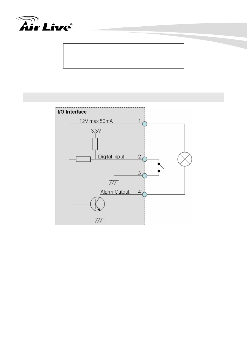
User can refer to the schematic below to make a proper connection between I/O connector
and external sensor and output device.
A.2 Explanation of External I/O Circuit Diagram
CAUTION!
• THE LOW VOLTAGE/CURRENT CIRCUITS AND HIGH VOLTAGE/ CURRENT
CIRCUITS ARE IN THE NETWORK CAMERA CIRCUIT. THE QUALIFIED ELECTRICIAN
SHOULD DO THE WIRING NOT BY YOURSELF. INCORRECT WIRING COULD
DAMAGE NWTWORK CAMERA. YOU COULD RECEIVE THE FATAL ELECTRIC
SHOCK.
• THE EXTERNAL I/O IS NOT CAPABLE OF CONNECTING DIRECTLY TO DEVICES
THAT REQUIRE LARGE AMOUNTS OF CURRENT. IN SOME CASES, A CUSTOM
INTERFACE CIRCUIT (CUSTOMER PROVIDED) MAY HAVE TO BE USED. SERIOUS
DAMAGE TO NETWORK CAMERA MAY RESULT IF A DEVICE IS CONNECTED TO
THE EXTERNAL I/O THAT EXCEEDS ITS ELECTRICAL CAPABILITY.
- AirMax5 (146 pages)
- AirMax5N (93 pages)
- AirMax5X (91 pages)
- AirVideo-100 (67 pages)
- AirVideo-100v2 (63 pages)
- AirVideo-2000 (31 pages)
- AP60 (101 pages)
- BT-201USB (63 pages)
- BT-302USB (52 pages)
- BU-3026 (64 pages)
- CamPro Professional (178 pages)
- CoreNVR 16 (55 pages)
- DS-100 (34 pages)
- DS-100 v2 (36 pages)
- ES-4000 v2 (168 pages)
- ES-6000 (221 pages)
- Ether-FSH2402NT (19 pages)
- Ether-FSH2422W (55 pages)
- Ether-GSH16TW (42 pages)
- Ether-GSH2404W (50 pages)
- Ether-GSH2416W (61 pages)
- Ether-GSH24T v.2 (16 pages)
- Ether-GSH24TW (42 pages)
- Ether-GSH8TW v2 (36 pages)
- EtherWe-1000U (15 pages)
- G.DUO (137 pages)
- HP-1000E v2 (13 pages)
- HP-2000E (29 pages)
- HP-3000E (15 pages)
- IAR-5000 v2 (202 pages)
- IAS-2000 (163 pages)
- IGR-1500 (78 pages)
- IGR-2500 (81 pages)
- Live-800G (16 pages)
- Live-GSH5T (25 pages)
- Live-GSH8T (25 pages)
- WFP-101U (133 pages)
- MU-5000FS A2 (42 pages)
- MW-2000S (225 pages)
- N.MINI (87 pages)
- N.Plug (103 pages)
- N.TOP (71 pages)
- NAS-235 (89 pages)
- NVR4 (85 pages)
- OD-2025HD (101 pages)