Appendix a: alarm i/o connector – AirLive VS-100 User Manual
Page 76
Appendix A. Alarm I/O Connector
73
AirLive VS-100 User’s Manual
A.1 Interfacing to the External I/O
Some features of the Video Server can be activated by an external sensor that senses
physical changes in the area device is monitoring. These changes can include intrusion
detection or certain physical change in the monitored area. For examples, the external
sensor can be a door switch or an infrared motion detector. These devices are customer
provided, and are available from dealers who carry surveillance and security products.
Electrically, they must be able to provide a momentary contact closure.
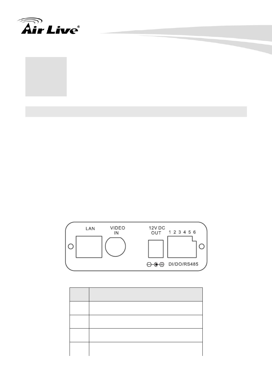
This device provides a general I/O terminal block with one digital input and one output for
device control. Pin 2 and 3 can be connected to an external sensor. The input voltage will
be monitored from the initial state ‘LOW’. If the external sensor need 12VDC power, it can
connect to Pin1 (50mA maximum). The Alarm Output of pin 3 and 4 can be used to turn on
or off the external device. Pin 5 and 6 are the D+ and D- of RS485 respectively.
Pin
Function
1
12VDC power supply (50mA maximum)
2 Digital
Input
3 GND
4 Alarm
Output
A
Appendix A: Alarm I/O
Connector