Installation, Connection, Status signalling – 2N Helios IP Safety User Manual
Page 30: Configuration
30
Installation:
Install the
onto a two-wire cable between the intercom
2N Helios IP Security Relay
®
and the electric lock inside the area to be secured (typically behind the door). The
device is powered and controlled via this two-wire cable and so can be added to an
existing installation. Thanks to its compact dimensions, the device can be installed into
a standard mounting box.
Connection:
Connect the
to the intercom as follows:
2N Helios IP Security Relay
®
To the intercom active output (OUT1 or OUT2) , or
To the intercom relay output with a 12 V DC serial external power supply.
Connect the electric lock to the
output as follows:
2N Helios IP Security Relay
®
To the active 12 V / 700 mA DC output, or
To the relay output with a serial external power supply.
The device also supports a Departure button connected between the ‘PB’ and ‘-
HeliosIP’ terminals. Press the Departure button to activate the output for 5 seconds.
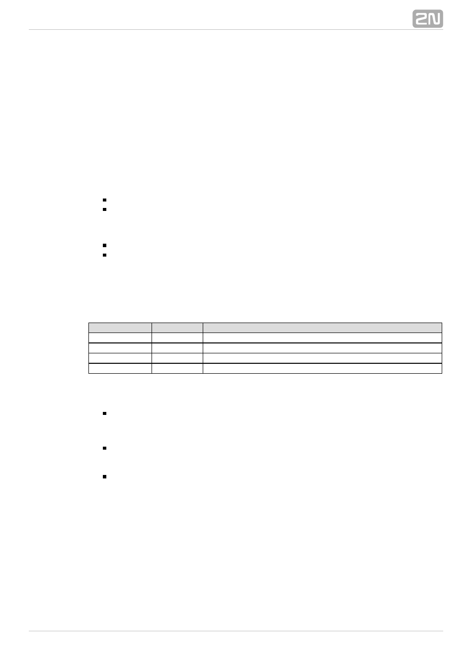
Status signalling:
Green LED
Red LED
Status
blinking
off
Operational mode
on
off
Activated output
blinking
blinking
Programming mode – waiting for initialisation
on
blinking
Error - wrong code received
Configuration:
Connect the
to the properly set intercom switch
2N Helios IP Security Relay
®
output; refer to the
. Make sure that one
2N Helios IP Configuration Manual
®
LED at least on the
is on or blinking.
2N Helios IP Security Relay
®
Press and hold the
Reset button for 5 seconds to
2N Helios IP Security Relay
®
put the device in the programming mode (both the red and green LEDs are
blinking).
Activate the intercom switch using the keypad, telephone, etc. The first code sent
from the intercom will be stored in the memory and considered valid. After code
initialisation, the
will pass into the operational
2N Helios IP Security Relay
®
mode (the green LED is blinking).