2N Omega Lite - Installation Manual v1.9 User Manual
Page 29
29
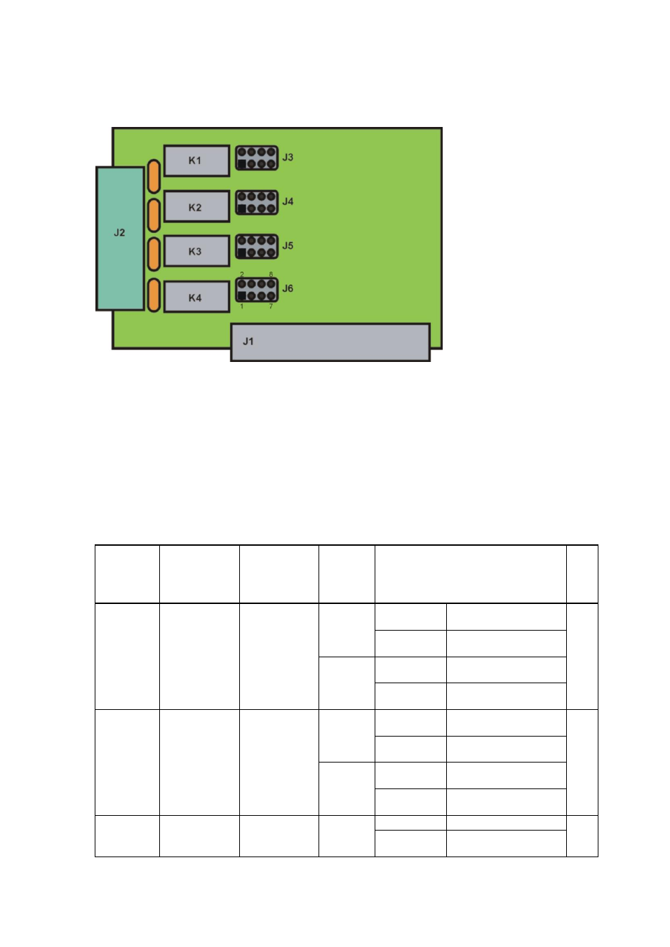
J1
- connector for connecting to motherboard (or extender module)
(connector is secured against incorrect connection by the blanking off
of PIN 5,6,7,8).
J2
- connector for connecting switch.
J3-J6
- setting array for individual switches.
K1-K4
-switching relay.
Output signal: max. 30V DC., 7mA;; parameters at output of internal OMEGA Lite source:
current source 10mA, +24V
Connection
number
description
Internal
source
connected?
Direction
out/in
OMEGA
Lite
Description
Shor
ting
pins:
1
relay output
without power
from OMEGA
Lite, floating
NO
OUT
rest:
open (disconnected
+ and -)
4+6
connected:
close (connected +
and -)
IN
rest:
open (disconnected +
and -)
connected:
close (connected +
and -)
2
relay output
without power
from OMEGA
Lite, floating
(inverse logic)
NO
OUT
rest:
close (connected +
and -)
1+2
connected:
open (disconnected
+ and -)
IN
rest:
close (connected +
and -)
connected:
open (disconnected +
and-)
3
relay output
with power
from OMEGA
YES
OUT
rest:
has no reason
5+6,
7+8
connected:
powers (+ earthed
on BGND)
- Analogue GSM gateway 2N EasyGate - Manual, 1575 v1.1.0.2 (69 pages)
- Fixed line replacement with 2N EasyGate - Quick Start, 1129 v1.5E (2 pages)
- Fixed line replacement with 2N EasyGate PRO - Quick Start, 1711 v1.01 (2 pages)
- Analogue GSM gateway 2N EasyGate PRO - Manual, 1749 v1.03 (79 pages)
- Fixed line replacement with 2N EasyGate PRO UMTS - Quick Start, 2018 v1.00 (2 pages)
- Analogue UMTS gateway 2N EasyGate UMTS USB - Quick Start (9 pages)
- Analogue UMTS gateway 2N EasyGate UMTS USB - User Manual, v1.00 (38 pages)
- Wireless 3G router 2N EasyRoute_old design - Quick start, 1526 v2.00 (2 pages)
- Wireless 3G router 2N EasyRoute_new design - Quick start, 1664 v1.00 (2 pages)
- Wireless 3G router 2N EasyRoute_new design - User manual, 1670 v1.06 (101 pages)
- Wireless 3G router 2N EasyRoute_old design - User manual, 1571 v1.06 (99 pages)
- Entrance guard 2N Helios - Manual - antivandal installation (2 pages)
- Design intercom 2N Helios - Guide mounting (2 pages)
- Door camera for 2N Helios - Installation manual - camera 9135210E (2 pages)
- Home intercom 2N Helios - Manual - display installation (5 pages)
- Electric lock for 2N Helios - Secondary switch - installation manual, 1360 v2.0 (2 pages)
- Door intercom 2N Helios - Manual, 1322 v3.0 (76 pages)
- Helios IP User manual, 1510 v1.13 (143 pages)
- Helios IP User manual, 1510 v1.12 (127 pages)
- Helios IP User manual, 1510 v1.11 (119 pages)
- Lift emergency phone 2N LiftNet - Manual, 1446 v1.8.3 (97 pages)
- Mobile Audio Gateway public address system - Quick start manual (2 pages)
- IVR Editor manual v1.0.2 (43 pages)
- Omega Lite PBX Assistant - manual v1.2 (57 pages)
- Omega series - Configuration Tool manual v1.10 (114 pages)
- IVR Editor manual v1.0 (43 pages)
- Omega series - Configuration Tool manual v1.9 (114 pages)
- Omega series - VoIP manual v1.4 (113 pages)
- Omega 48 - Basic Services v1.0 (60 pages)
- Omega 48 - Installation Manual v1.0 (48 pages)
- Omega 48 - Operator Services v1.0 (48 pages)
- StarPoint 500 - manual v2.0 (32 pages)
- Omega Lite - Configuration Tool manual v1.6 (101 pages)
- Omega Series - Voicemail v1.0 (31 pages)
- Omega Lite - Configuration Tool manual v1.8 (112 pages)
- Omega Lite - Configuration Tool manual v1.7 (112 pages)
- Omega Series - Basic Services (60 pages)
- Omega Lite - Installation Manual v1.5 (53 pages)
- Omega Series - Operator Services (48 pages)
- Omega Lite Panel - manual v1.0 (34 pages)
- Omega Lite PBX Assistant - manual v1.0 (49 pages)
- Omega Lite - Quick Guide v1.0 (1 page)
- Omega Series - VoIP manual v1.2 (88 pages)
- Lift emergency phone 2N SingleTalk - Manual, 1514 v6.3.0 (73 pages)