Omega 48 installation manual – 2N Omega 48 - Installation Manual v1.0 User Manual
Page 24
2N
®
- OMEGA 48
Installation manual
Installation manual
24
6.6. Module GSM 900/1800/1900 Mhz pro 1-2 GSM
Order No 1880041 – for 1 GSM connection MC55/MC55i
Order No 1880042 – for 2 GSM connection MC55/MC55i
Order No 1880043 – for 1 GSM connection MC56/MC55i
Order No 1880044 – for 2 GSM connection MC56/MC55i
The module GSM is fitted in a free position like any other interface and is
intended for connecting one or two lines to the GSM network.
For the module with two GSM lines, both connected GSM work independently.
An independent SIM card must be inserted for each line SIM (the SIM card holder is
attached to the platelet of the GSM module GSM).
The basis for the GSM module is an industrial triband GSM module SIEMENS
MC55 (or MC56 – triband USA).
Only one antenna with an SMA connector is attached to the GSM module
(located on the module platelet).
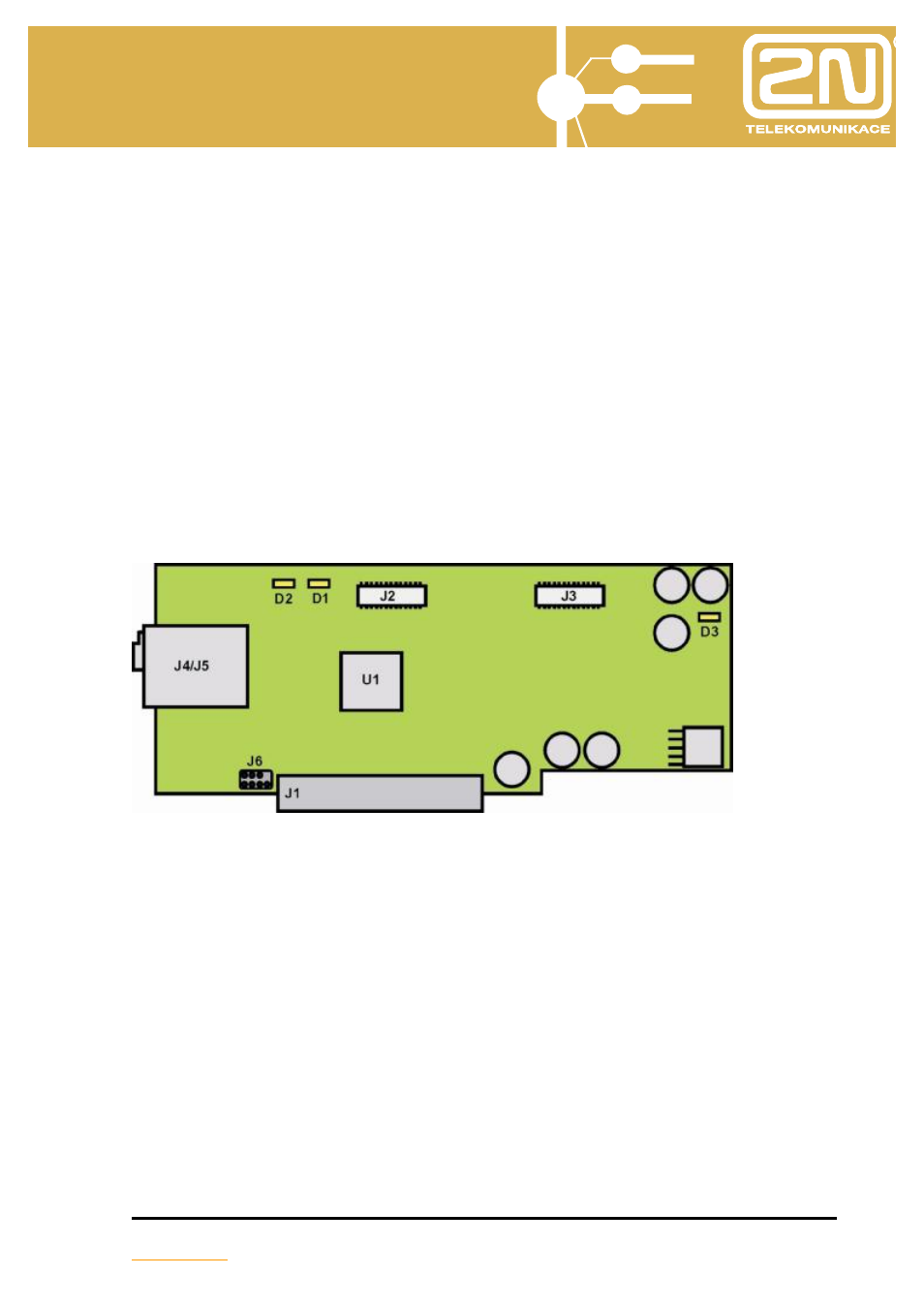
J1
- connector for connecting to motherboard (or extender module)
(connector is secured against incorrect connection by the blanking off
of PIN 5,6,7,8).
J2
- connector for connecting GSM module Siemens MC55/55i/56
(PORT 2).
J3
- connector for connecting GSM module Siemens MC55/55i/56
(PORT 1).
J4-J5
- connector for inserting SIM cards (SIM1/SIM2)
J6
- company servicing reanimation connector (SW do CPU).
D1
- signalling LED (login, GSM fault- PORT 1).
D2
- signalling LED (login, GSM fault - PORT 2).
D3
- signalling LED (power of module).