Omega 48 installation manual, Interface modules – 2N Omega 48 - Installation Manual v1.0 User Manual
Page 17
2N
®
- OMEGA 48
Installation manual
Installation manual
17
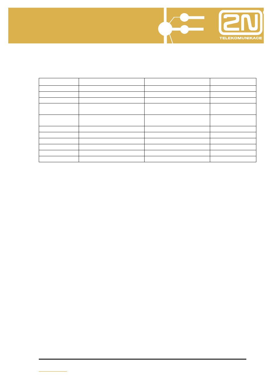
6. Interface modules
Order No
Name of module
Internal designation 2N
Total number
1880030
Module 2x internal line
OL2VL
24
1880038
Module 2x system digital
telephone
OL2SYSD
10
1880039
Module 2x system telephone
OL2SYS
10
1880031
module 1x external line / 1x
internal line
OCOVL
24
1880032
module 1x external line
receiver 16kHz / 1x internal
line
OCOVL16
24
1880041
module GSM 1x MC55
OL2GSM
6
1880042
module GSM 2x MC55
OL2GSM
6
1880043
module GSM 1x MC56
OL2GSM
6
1880044
module GSM 2x MC56
OL2GSM
6
1880020
module ISDN S
0
OLISDN
6
1880021
Module VoIP
OLIP8
1
General features
A line module generally contains two interfaces. One exception is the module S
0
,
which contains one interface (but which carries two calls at the same time) and combined
module of external and internal line. Modules are equipped with overvoltage protection
and can be fitted to the motherboard or extender module in any order. All modules are
equipped with an identification system allowing the program of the PBX to ascertain the
concrete configuration immediately after switching on. All module connectors contain two
pairs of blanked holes (without contacts). This measure prevents the incorrect insertion of
modules.
All modules can be fitted up to the maximum number of vacant positions (12 = 6
motherboard + 6 extender module).
RJ45 connectors for connecting local circuits are a part of line modules. The
module is secured against movement by a screw in the connected strip.