Operator’s cab – JLG G6-42A Operator Manual User Manual
Page 20
A brief description of controls and
instruments is provided here as a
convenience for the operator.
These descriptions DO NOT
provide complete operation
instructions. Read & understand
this Manual and the GRADALL
Material Handler Safety Manual.
WARNING
!
3.1
Accelerator Pedal: Depress pedal to increase speed and release pedal to
decrease speed.
Attachment Tilt Lever: This lever controls tilt of the fork carriage. Speed is
proportional to lever actuation and engine RPM. Push lever forward to tilt down;
pull lever back to tilt up.
Attachment Tilt Switch (optional): Depress left side of switch to tilt down;
depress right side of switch to tilt up.
Auxiliary Control Lever (optional): This lever is used to control optional
hydraulic attachments. Follow decal instructions for lever/handler movements.
Auxiliary Light Switch (optional): This switch turns auxiliary lights on and
off.
Boom Control Joystick: This joystick controls boom elevation and extension.
Pull joystick back to raise boom; push joystick forward to lower boom. Move joystick
to right to extend boom; move to left to retract boom. Speed of boom movement
is proportional to joystick actuation and engine RPM.
Engine Coolant Temperature Gauge: This gauge displays engine coolant
temperature.
Engine Oil Pressure Gauge: This gauge displays engine oil pressure.
Fuel Gauge: This gauge displays level of fuel in fuel tank.
Heater Fan Switch (optional): This switch turns heater fan on and off.
Horn Button: Depress button to sound horn.
Hourmeter: This meter indicates total time of engine operation in hours and
tenths of hours.
Ignition Switch: This switch is actuated by a key. In “ACC” or “RUN” position,
voltage is available for all electrical functions. Full clockwise rotation to “START”
engages starter motor. Counter-clockwise rotation to “OFF” stops engine and
removes voltage from all electrical functions.
Level Indicator: This bubble level indicator enables the operator to determine
the left to right level condition of the handler.
Lights Switch (optional): This switch controls optional lighting which may be
provided with the handler.
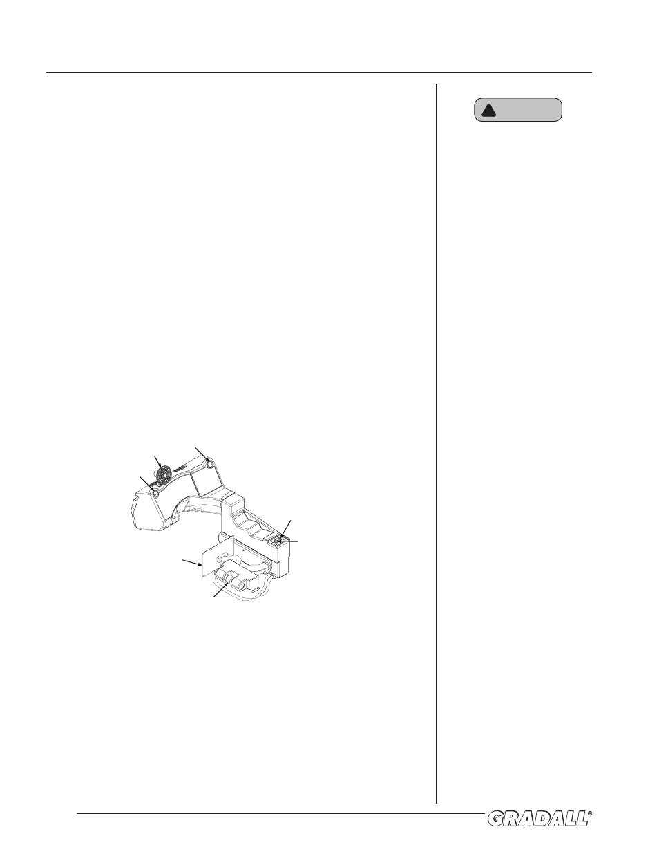
DEFROSTER FAN
AIR VENT
AIR VENT
TEMPERATURE CONTROL
HEATER FAN SWITCH
ACCESS COVER/
HEATER VENT
HEATER
OPERATOR’S CAB