Mechanical brake release, Mechanical brake release -14, Manual disengage -14 – JLG 3246ES Operator Manual User Manual
Page 64
SECTION 4 - MACHINE OPERATION
4-14
– JLG Lift –
3121165
Mechanical Brake Release
Machines, USA built prior to s/n 0200118041:
Machines, Belgium built prior to s/n 1200001487:
1. Chock wheels or secure machine with tow vehicle.
2. Power machine in ground mode.
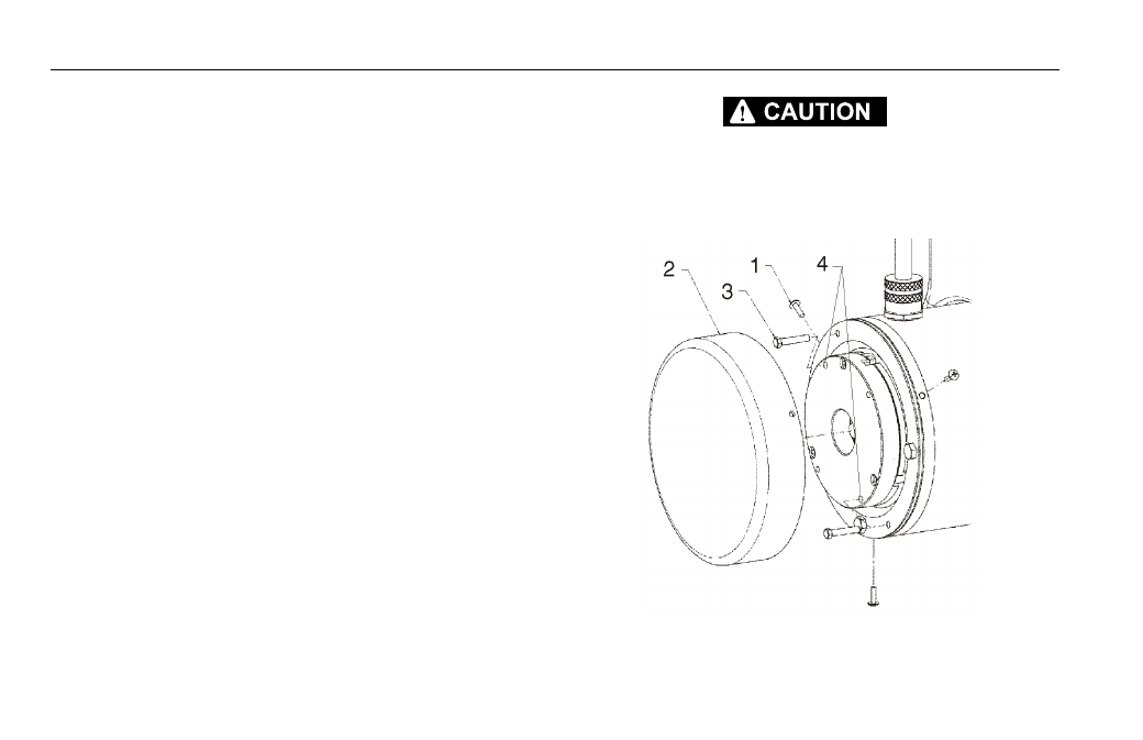
3. Remove the three cover bolts (1), from the back of drive
motor unit.
4. Remove brake cover (2).
5. Locate the 2 disengage bolts (3) that are stored in the
motor end cap. Remove bolts and insert them into the two
disengage holes (4) in the brake housing, see Item 4 in
Figure 4-4., Manual Disengage.
6. Tighten down the bolts and the brake on that drive motor
will disengage.
7. Repeat this procedure on opposite wheel drive. With both
drive motor brakes now disengaged, the machine can be
moved manually.
8. After towing is complete, chock wheels and remove 2 dis-
engage bolts (3) from disengage holes (4). Insert bolts
back into original holes in motor end cap.
9. Reinstall cover (2).
AFTER THE MACHINE IS TOWED, THE DISENGAGE BOLTS MUST BE REMOVED
FROM THE BRAKE DISENGAGE HOLES. THE BRAKES CANNOT BE ENGAGED
WITH THE DISENGAGE BOLTS IN THE BRAKE DISENGAGE HOLES. THIS WILL
CAUSE THE MACHINE TO ROLL WHEN PARKED ON AN INCLINE.
Figure 4-4. Manual Disengage