Psl™ box and ground control locations, Machine power up using the psl, Machine power down – JLG DVSP Series Operator Manual User Manual
Page 38: Changing the operator’s code, Psl™ switch controls & indicators -18, 10 progammable security lock (psl, Dvl/dvsp - option)
SECTION 3 - MACHINE CONTROLS, INDICATORS AND OPERATION
3-18
– JLG Lift –
3121135
3.10 PROGAMMABLE SECURITY LOCK
(PSL
™
) (DVL/DVSP - OPTION)
The optional Programmable Security Lock switch can be
programmed with a four (4) digit operators code to allow
only those persons with the code to power-up and oper-
ate the machine.
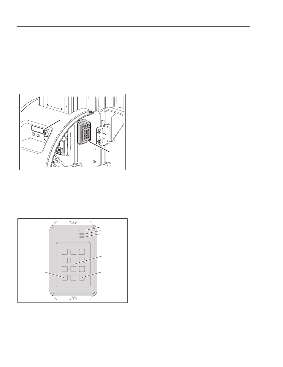
PSL™ Box and Ground Control Locations
Machine Power Up using the PSL™
NOTE: When entering code on the key pad, a short beep
indicates a properly depressed key, a long beep indi-
cates an error in depressing key. If an error occurs,
you must restart the code entry process again.
1. Enter the four digit code on the PSL key pad. The
ACCEPT - AMBER LED indicator will be lit if the code is
correct.
2. Press the keypad ON button. The ON - GREEN LED
indicator will light and power will be supplied to the
Ground Control Station.
3. At the ground control station, turn the main power
selector switch from OFF to either Platform Control
Mode or Ground Control Mode.
4. The machine will now operate normally.
Machine Power Down
1. At the Ground Control Station set the main power
selector switch to the OFF position.
2. Press the OFF button on the PSL keypad. No LEDs on
the PSL box will be lit.
Changing the Operator’s Code
The PSL Operators Code can be changed by a supervisor
should the need occur. A separate permanent Supervi-
sor’s Code matched to the serial number of the PSL box is
included on a sheet in the PSL user manual supplied with
the machine.
1. Enter the Supervisor’s code on the key pad. The PRO-
GRAM - RED LED will be lit if correct code is entered.
NOTE: ON or OFF cannot be one of the four digits of the
new Operator’s code.
2. Enter a new four (4) digit Operator’s code on the key-
pad. The ACCEPT - AMBER LED will light up if the new
Operator’s code is accepted.
3. Press the OFF button on the keypad to activate the
new Operator’s code.
NOTE: The new Operator’s code will remain in the PSL even
when power is removed from the equipment, or until
the Supervisor changes the Operator’s code.
Figure 3-6. PSL
™
Switch & Ground Control Station
Locations - At Rear of Machine.
1. PSL Switch (Inside Right Cover) (a)
2. Ground Control Station
Note: (a) Machines with bolt on (fixed) covers, the PSL
Switch is mounted on outside of right cover.
Figure 3-7. PSL
™
Switch Controls & Indicators.
1. ON (Green LED)
4. Key Pad
2. ACCEPT (Amber LED)
5. OFF Switch
3. PROGRAM (Red LED)
6. ON Switch
1
2
PSL
™
1
2
3
4
5
6
7
8
9
0
4
5
1
2
3
6