Platform on/off key switch, Platform emergency stop/shut down button, Platform control display panel – JLG DVSP Series Operator Manual User Manual
Page 32: Platform control display panel -12
SECTION 3 - MACHINE CONTROLS, INDICATORS AND OPERATION
3-12
– JLG Lift –
3121135
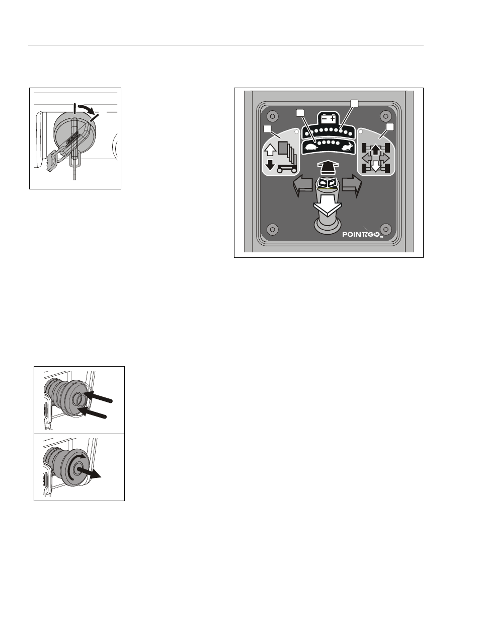
Platform On/Off Key Switch
Set the ON/OFF Key Switch to the OFF position to power
machine down.
NOTE: If necessary, when machine is not in use, remove
key from platform key switch to disable machine from
unauthorized use.
NOTE: During operation the operator in the platform can
prevent unauthorized control of the machine (from
the Ground Control Station) by either switching the
On/Off Key to the OFF position, or activating the
Emergency Stop Button on the platform control con-
sole.
Platform Emergency Stop/Shut Down Button
NOTE: The Platform and Ground Control Station Emer-
gency Stop/Shut Down Buttons must both be in the
RESET position to operate machine.
Platform Control Display Panel
1. Battery Charge/Flash Code Indicator LEDS
On normal power-up and operation this series of ten
(10) LEDs visually indicates the amount of charge
remaining in the batteries.
The number of LEDs lit will change depending on the
level of charge in the batteries.
• (+) All Three (3) GREEN LEDs lit up indicate maxi-
mum battery charge.
• Four (4) YELLOW LEDs indicate a two thirds to one
third battery charge remaining.
• (–) Three (3) RED LED’s lit indicate minimum battery
charge remaining. The machine will continue to
operate at this charge level but will begin to indicate
low battery voltage warning indicators.
NOTE: For more information on Battery Warning Level Indi-
cators See “Battery Low Voltage Warning Indicators”
on page 3-3.
This set of ten (10) LEDs will also indicate a flash (fault)
code if operating problems are detected by the
Ground Control Station.
NOTE: LED Flash (Fault) Code indications that can be cor-
rected by the operator are shown on Table 3-3 on
page 3-7, this section of the manual.
At the Platform Control Console -
Set the On/Off Key Switch to the
ON position (2) to operate
machine.
1. OFF Position
2. ON Position
POWER OFF
PUSH IN -
TO ENGAGE
Emergency Stop
POWER ON
TURN CLOCKWISE
and RELEASE to
RESET Emergency Stop
1
2
Figure 3-4. Platform Control Display Panel.
1. Battery Charge/Flash Code LEDS
2. Drive Mode Indicator
3. Lift Mode Indicator
4. Drive Speed Setting
Indicator
3
1
4
2