Figure 3-2, Throug – Blade ICE G8000 User Manual
Page 53
RackSwitch G8000 Application Guide
Chapter 3: VLANs
53
BMD00041, November 2008
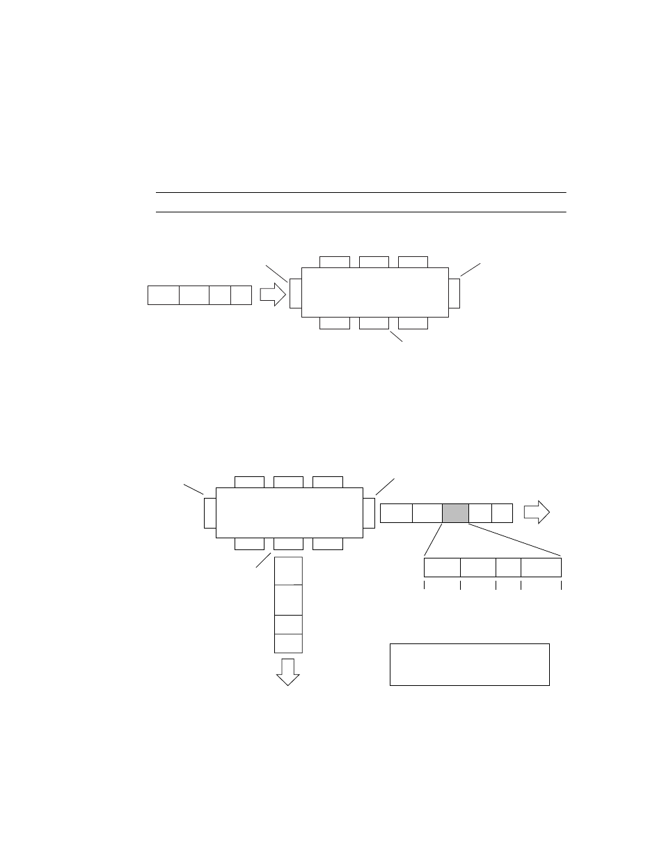
illustrate generic examples of VLAN tagging. In
untagged incoming packets are assigned directly to VLAN 2 (PVID = 2). Port 5 is configured
as a tagged member of VLAN 2, and port 7 is configured as an untagged member of VLAN 2.
N
OTE
– The port assignments in the following figures are not meant to match the G8000.
Figure 3-2 Port-based VLAN assignment
As shown in
, the untagged packet is marked (tagged) as it leaves the switch through
port 5, which is configured as a tagged member of VLAN 2. The untagged packet remains
unchanged as it leaves the switch through port 7, which is configured as an untagged member
of VLAN 2.
Figure 3-3 802.1Q tagging (after port-based VLAN assignment)
Port 6
DA
SA
Data
CRC
BS45011A
Port 7
Port 8
Port 1
Port 4
Port 5
Port 2
Port 3
802.1Q Switch
PVID = 2
Untagged packet
Untagged member
of VLAN 2
Tagged member
of VLAN 2
B
efore
BS45012A
Port 6
Port 7
Port 8
Port 1
Port 4
Port 5
Port 2
Port 3
802.1Q Switch
Key
Priority
CFI
VID
- User_priority
- Canonical format indicator
- VLAN identifier
PVID = 2
Tagged member
of VLAN 2
Untagged memeber
of VLAN 2
After
DA
SA
Data
CRC
(*Recalculated)
Outgoing
untagged packet
(unchanged)
DA
SA
Data
CRC*
Tag
VID = 2
Priority
16 bits
3 bits
1 bits
12 bits
8100
CFI