Snorkel TB126J User Manual
Page 33
6. CONTROLS
6 - 6
P/N 0191915
1 3
1 2
12. LIFT/SWING CONTROLLER:
UP: Slowly push the LIFT/SWING controller
forward and the main-boom raises. The further
forward you push the controller the faster the
main-boom raises.
DN: Same as UP only the main-boom goes down.
CW: Slowly push the LIFT/SWING controller to the
left and the turntable swings clockwise (from
above). The further left you push the controller the
faster the turntable swings.
CCW: Same as CW only the turntable swings
counterclockwise.
13. DRIVE/STEER CONTROLLER:
DRIVE FORWARD: Slowly push the
DRIVE/STEER controller forward and the TB126J
moves forward. The further forward you push the
controller the faster the TB126J goes (max. 3
mph, 4.8 km/hr).
NOTE: There are blue and yellow arrows on top
of the chassis. The blue arrows point to the
FORWARD end of the chassis and to the LEFT
side of the TB126J. The yellow arrows point to
the REVERSE end of the chassis and to the
RIGHT side of the TB126J. The DRIVE/STEER
controller is color coded to match the arrows.
The color coding is designed to keep you from
becoming disoriented when you are aloft and
the platform is rotated with respect to the
chassis.
DRIVE REVERSE: Same as DRIVE FORWARD
except the TB126J moves backward.
STEER RIGHT: Slowly push the DRIVE/STEER
controller to the right and the front wheels move in
the direction for a right hand turn. The longer you
hold the controller to the right the further the
wheels turn.
STEER LEFT: Works the same as STEER RIGHT
only for a left hand turn.
NOTE: The wheels stay the direction you turn
them, they do not automatically return to center
the way automobile wheels do.
T
CHASSIS
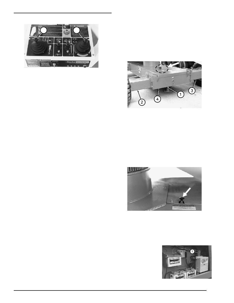
1. AXLES:
RAISE: Lowers the jack (1) and raises the chassis (4).
LOWER: Raises the jack and lowers the chassis.
EXTEND: Extends both rear axles (2) (3).
RETRACT: Retracts both rear axles.
NOTE: The axles extend or retract one at a
time, not simultaneously.
For the AXLES controls to work BOOMS/AXLES
SWITCH must be set to AXLES and the
SELECTOR SWITCH set to GROUND. Also, the
main boom must be down and retracted.
2. HIGH RANGE SPEED SELECTOR VALVE:
This valve works with the DRIVE RANGE switch,
on top the platform-control box, to determine the
maximum speed the chassis can travel along the
ground. See DRIVE RANGE switch above for a
table of settings and speeds.
T
TURNTABLE
BATTERY:
When the BATTERY
switch (1) is set to
OFF, all of the
batteries are
disconnected from the
electrical system.