Guardrail system 7-8, Lanyard anchors 7-8, Operating controls 7-8 – Snorkel SP22 User Manual
Page 42: Emergency stop 7-8, Emergency power 7-8, Rcd / elcb outlet 7-8, Chapter 7. pre-operational inspection
❑
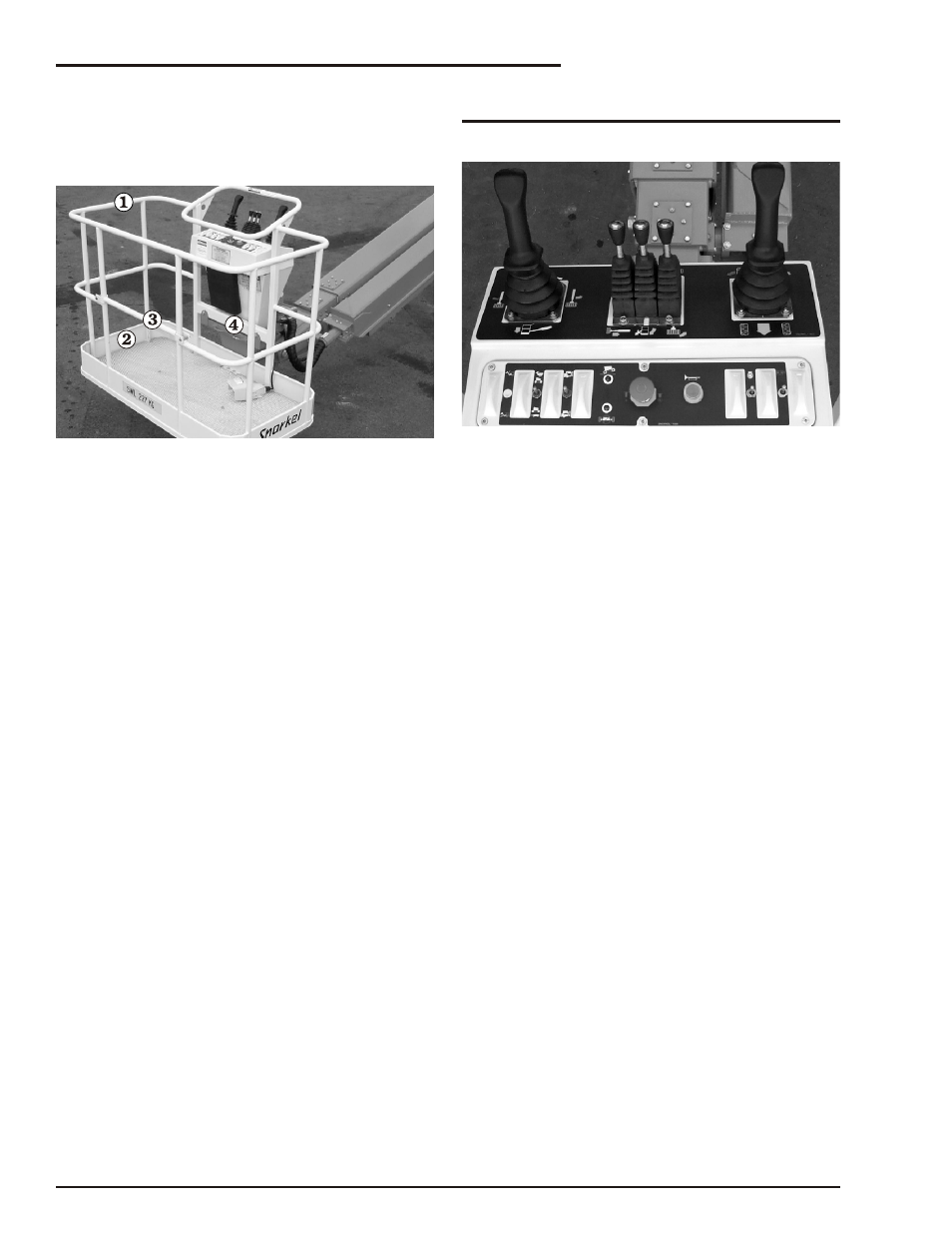
Guardrail System
The guardrail system (refer to Figure 6.17)
includes the top rail, mid rail, toeboards and a
gravity gate or optional swinging gate.
Figure 6.17—Guardrail System
Inspect all components of the guardrail system.
The rails and toeboards must all be in place
and free of any damage or deformation. Visually
check the rail and toeboard welds for cracks. All
bolts and nuts fastening the guardrails in place
must be present and not show any signs of
looseness.
Inspect the gravity gate to be sure it is present, is
not damaged, and moves freely.
Inspect the optional swinging gate to see that it
swings freely, closes firmly, and is not deformed in
any way. Make sure the latch closes and secures
the gate when the gate is closed.
❑
Lanyard Anchors
There are two lanyard anchors below the upper
control panel (refer to Figure 6.17).
Visually inspect the lanyard anchors to make sure
they are in place, are not deformed and are
securely fastened to the platform.
❑
Operating Controls
Place the battery disconnect switch in the on
position and pull the emergency stop button out on
the lower control panel.
From the upper controls, test the platform foot
switch by selecting a boom function and moving
the boom joystick without stepping on the foot
switch. If movement occurs the interlock is not
functioning properly. Do not operate the machine
until the problem is corrected.
Test the operation of each control in both directions
from the upper controls (refer to Figure 6.18).
Note
The SP20 does not have a jib boom.
Figure 6.18—Platform Controls
❑
Emergency Stop
Push the red emer gency stop but ton in to turn off
the en gine. The up per con trol func tions should not
op er ate with the emer gency stop in this po si tion.
❑
Emergency Power
Place the bat tery dis con nect switch in the on po si -
tion and pull the emer gency stop but ton out to turn
on the elec tri cal power. Operate the emer gency
power switch to op er ate the ae rial plat form from the
up per con trols us ing the emer gency power sys -
tem. Horn
Depress the horn button on the right side of the
upper control panel to ensure that it sounds to warn
personnel in the area.
❑
RCD / ELCB Outlet
The RCD (Re sid ual Cur rent De vice) is lo cated at
the ground and will pro tect against short cir cuits to
earth. (Re fer to Fig ure 6.19) When there is a short
cir cuit the RCD will shut down the 230v AC power
to the plat form out let.
To re set the out let dis con nect the power tool lead
from the plat form box and re set the RCD at the
ground.
If the prob lem per sists call a trained ser vice tech ni -
cian.Figure 6.19—Power-Input Con nec tor
The electrical outlet on the platform, and its power
cable, are designed to supply 2 kW of continuous
duty power to run power tools of various sorts.
The power can come from either the optional AC
generator, or from an electrical source outside the
SP. If you use an electrical source outside the SP
page 7 - 8
SP20/SP22 – 11890A
Chapter 7. Pre-operational Inspection