Snorkel S3219E-sn000017+ User Manual
Page 33
Chapter 8 – Prestart Inspection
S3219E/S4732E – 1500834
29
To steer to the right, hold down the right side of
the steer switch.
To steer to the left, hold down the left side of the
steer switch.
7. Test the operation of the brakes while operating the
aerial platform from the upper controls. The brakes
are engaged when:
the joystick interlock is released.
the drive/lift selector switch is in the lift position.
the emergency stop button is pushed down.
Placing the drive/lift selector in the drive position, en-
gaging the interlock and moving the joystick, releases
the brakes.
8. Place the drive/lift selector switch in the lift position
and test the operation of the joystick in both direc-
tions. The drive functions should not operate with the
selector in the lift position.
Squeeze and hold the interlock switch against the
joystick. Test the joystick in both directions.
To raise the platform, pull the joystick backward.
To lower the platform, push the joystick forward.
Emergency Stop
To test the emergency stop button from the upper con-
trols:
1. Push the emergency stop button inward to turn off
electrical power.
2. Verify that the upper control platform and drive func-
tions do not operate.
Horn Button
The horn is operational when the machine is set up for
operation from the upper control panel (refer to Figure
8.18).
Press the horn button to ensure that it sounds to warn
personnel in the area.
Lowering Alarm
To test the lowering alarm from the upper controls:
1. Raise the platform approximately 10′ (3 m).
2. Lower the platform and make sure the alarm sounds.
Drive Alarm
Drive in both the forward and reverse directions to ensure
that the alarm sounds to warn personnel in the area that
the aerial platform is in motion.
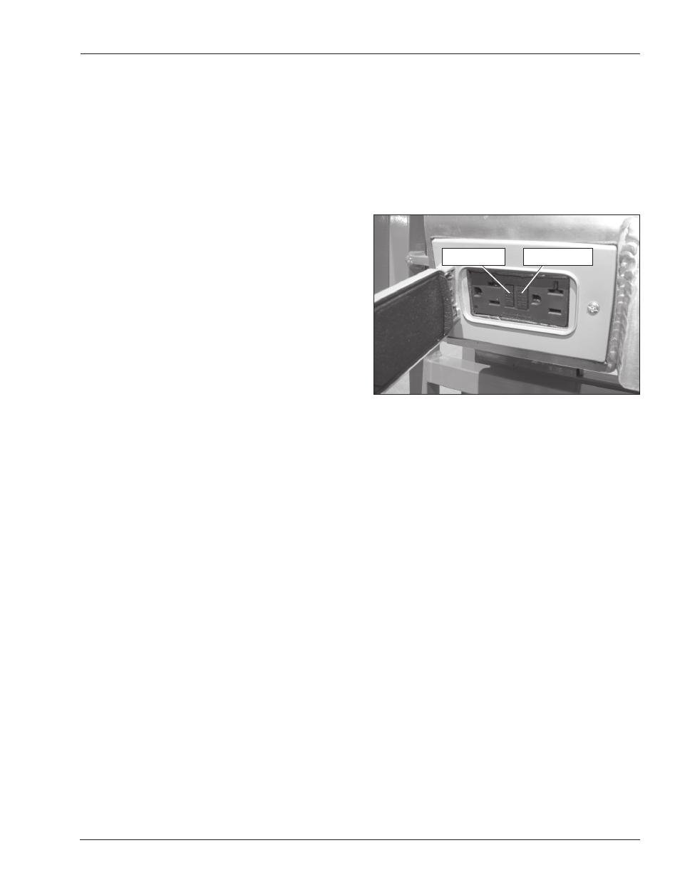
Electrical Power Outlet
Connect a source of 125 volt AC power to the power-input
connector at the rear of the chassis. Plug an electrical
tool into the receptacle and try to operate the tool to verify
proper operation of the outlet.
Use the following procedure to test the ground fault circuit
interrupter GFCI.
1. Push the test button (refer to Figure 8.19).
Figure 8.19 – Electrical Power Outlet
2. Plug an electrical tool into the outlet and verify the
power is off.
If the power was off, push the reset button to
restore power.
If the power was on, repair or replace the re-
ceptacle.
Flashing Light
The machine may be equipped with an optional flashing
light mounted on the side of the machine.
To inspect the flashing light:
1. At the lower controls, pull the emergency stop button
outward and turn the control select/ground operation
switch to either the lower or upper control position.
2. Operate any control function and visually check to
see that the light is flashing approximately one flash
per second.
Note
There is not an off switch for the flashing light.
Test Button
Reset Button