Danger – Snorkel S2033CE User Manual
Page 22
Chapter 7 – Controls
18
S2033 – 330003EE
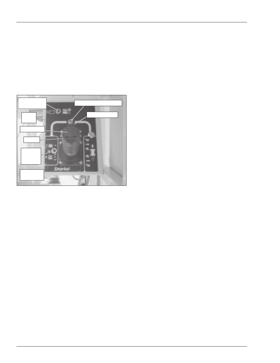
Upper Controls
The upper controls (refer to Figure 7.2) are located on the
control box at the platform. The following controls are
located at the upper control station.
• Emergency stop button
• Drive/lift selector switch
• Joystick to control platform lift, drive and steer
The battery condition indicator gauge may also be lo-
cated at the upper control station.
Figure 7.2 – Upper Controls
Emergency Stop Button
The emergency stop is a two-position red push button on
the front of the upper control box. Push the button in to
disconnect power to all control circuits at the upper con-
trols. Pull the button out to restore power.
Note
The lower controls override the upper controls. If the up-
per control emergency stop is engaged the lower con-
trols can still be used to operate the aerial platform.
Push the button in when the upper controls are not in use
to help protect against unintentional platform operation.
Drive/Lift Selector Switch
Place the drive/lift selector switch in the drive position to
drive the aerial platform using the joystick. The platform
will not raise or lower while driving.
Place the drive/lift selector switch in the lift position to
raise and lower the platform using the joystick.
Joystick
Use the joystick to operate the following functions.
• Aerial platform steering
• Aerial platform drive and speed
• Platform raise/lower and speed
Movement of the joystick in a given direction produces a
corresponding movement of the aerial platform. The steer-
ing and drive functions may be operated separately or
simultaneously.
Interlock
The joystick has an interlock switch in the handle. En-
gage the interlock by grasping the joystick and pulling
the switch toward the handle. Engage the interlock to
activate the steering, drive, or lift functions.
Steer Switch
The steer switch is a momentary contact, rocker switch
on top of the joystick. This switch controls the two front
wheels to steer the aerial platform.
To steer to the right, engage the interlock on the joystick
and hold down the right side of the steer switch. To steer
to the left, engage the interlock on the joystick and hold
down the left side of the steer switch.
Note
The steering wheels are not self-centering. Set the steer-
ing wheels straight ahead after completing a turn.
Low Voltage Warning Light
When the battery voltage of the batteries falls to a preset
level too low for proper machine operation, the following
happens.
• The low voltage warning light illuminates
• An alarm sounds
• The platform will not raise
Lower the platform to the stowed position when the warn-
ing light is on and the alarm is activated. Drive to a bat-
tery recharging area and fully recharge the batteries be-
fore returning the aerial platform to service.
When the load in the platform is near or at rated capac-
ity, an alarm will sound and the red light on the upper
controls (refer to Figure 4.7) will flash.
The alarm and light warn the operator that the platform is
close to becoming overloaded. All functions remain fully
operational.
A
Danger
The aerial platform can tip over if it becomes un-
stable. Death or serious injury will result from a tip-
over accident. Do not exceed the capacity values
indicated on the platform rating placard.
If the platform is fully lowered and is overloaded, when it
is elevated just past 1.8 m (6
′), a control module will stop
the lift and drive functions and the alarm will sound and
the warning light will flash. The platform can still be low-
ered to remove the excess load.
Steer Switch
Joystick
Emergency
Stop Button
Interlock Switch
Drive/Lift Selector Switch
Low Voltage
Warning Light
Horn
Button
Overload
Warning
Light