Routine service, See figure 8 installation, Removal – Snorkel X Series-sn6013-15019 User Manual
Page 7
7
Routine Service
Use the following table as a guide for routine maintenance,
refer to the Service Manual for complete service instructions.
SERVICE OPERATION
INTERVAL
Monthly 6 Months 2 Years
Daily
or
or
or
50 Hrs. 250 Hrs. 1000 Hrs.
Clean entire work platform
X
Check battery fluid level
X
Charge batteries
X
Check tires for damage
X
Check lug nuts/bolts
X
Check hydraulic fluid level
X
Check for peeling, faded or
X
missing labels & replace
Check deck and guardrail
X
fasteners for proper torque
Inspect elevating assembly
X
for bends or cracking
Check for & repair collision
X
damage
Check emergency lowering
X
valve operation
Check electric motor brushes
X
Check pivot pin bolts for
X
proper torque
Change hydraulic filter
X
Check all fasteners for
X
proper torque
Change hydraulic fluid
X
Grease front spindle bearings
X
Grease pot hole protection cylinder
rod end bearing
X
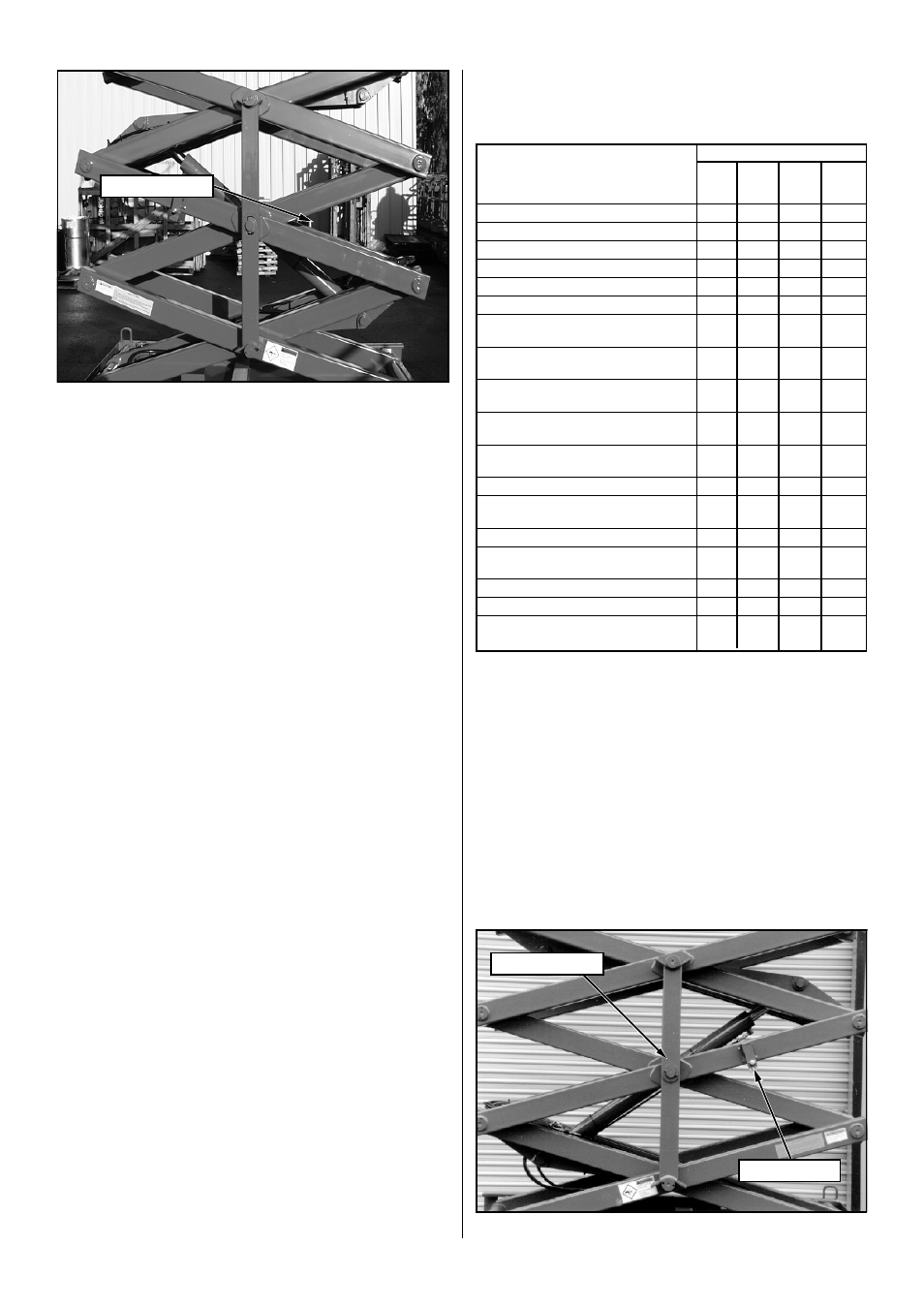
See Figure 8
Installation
1.
Park the work platform on firm level ground.
2.
Verify both Emergency Stop Switches are ON.
3.
Turn Chassis Key Switch to CHASSIS.
4.
Position Chassis Lift Switch to UP and elevate platform
approximately nine (9) feet (2.7 m), leaving enough room
to freely rotate the Scissors Brace.
5.
Pull out on the retaining pin and rotate the Scissors Brace
into vertical position.
6.
Push Chassis Lift Switch to DOWN position and gradually
lower platform until the upper and lower pivot pins rest on
the Scissors Brace.
Removal
1.
Push Chassis Lift Switch to UP position and gradually
raise platform until the Scissors Brace will clear the pivot
pins.
2.
Rotate the Scissors Brace counterclockwise until it locks
into position parallel with the scissor arm.
3.
Push Chassis Lift Switch to DOWN position and com-
pletely lower platform.
Figure 8: Blocking Elevating Assembly (X32N)
Retaining Pin
Scissors Brace
Figure 7: Blocking Elevating Assembly
(X20N, X20W, X26N)
Scissors Brace