Snorkel PAM26-sn000001+ User Manual
Page 22
December 2008
Instruction Manual
Page16
C
D
Ite
m
Model
mm
mm
1
PAM21
1740 1786
2
PAM26
1740 1786
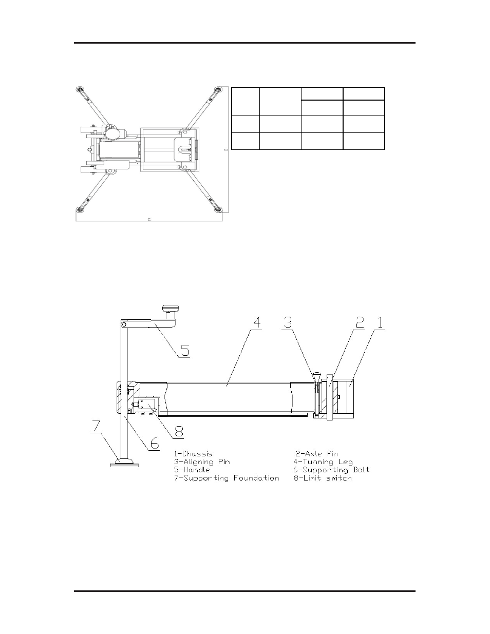
5.2.2 Area Needed For Set up the Machine
The area for machine stabilizer footprint shown as the sketch below:
5.2.3 Supporting and Leveling the Unit
There are horizontal forces including operating force and outer wind force etc. on the
platform. If excessive, render the platform unstable. Preventing inclination of the unit
is achieved by extending the four turning stabilizers, which are connected to the four
corners of the chassis. Supporting and leveling the unit is achieved by adjusting the
support bolts of the four turning stabilizers.
The sketch below shows the following parts:
1
The instructions for operation are as follows:
1. Pull up the aligning pin, extend outwards the turning leg, which is connected to
one of the four corners of the chassis, until the aligning pin gets into the working
aligning hole automatically.
2. Turn the handle clockwise until the supporting foundation contacts the ground for
all the four bolts, go on turning to make the road wheel away from the ground.
3. Adjust the leveling by observing the spirit level on the chassis. The bubble should
move to the center circle of the gauge when the chassis is set on an even plane.