Removal of the device / shutdown after operation – Lukas P 660 SG User Manual
Page 17
17
8.3 Controlling the valves
Two switches are provided on the valve. Each switch is assigned to the pressure connection
beneath it. By À ipping the respective switch, the pressurisation of the corresponding pressure
line can be controlled.
There are 2 control stages for each switch:
0 = Depressurised circulation (no pressure supply of the hydraulic line)
0 = Pressure supply of the pressure line
9. Removal of the device / Shutdown after operation
After the work is completed and before shutting down the unit, you should bring all connected
rescue devices into the basic position (storage position). Then you can stop the motor of the
unit.
Couplings:
If the connected hose lines are supposed to be removed during shutdown, decouple the
monocouplings as described in the chapter "Connection of the hose lines". Ensure that you
place the dust caps again on the monocouplings.
Clean the hydraulic unit before storing it to remove dirt caused by the use.
With a longer storage time, the outside of the device should be cleaned and the mechanical
moving metal parts need to be oiled. You should also drain the fuel from the tank.
Avoid storing the hydraulic units in a damp environment.
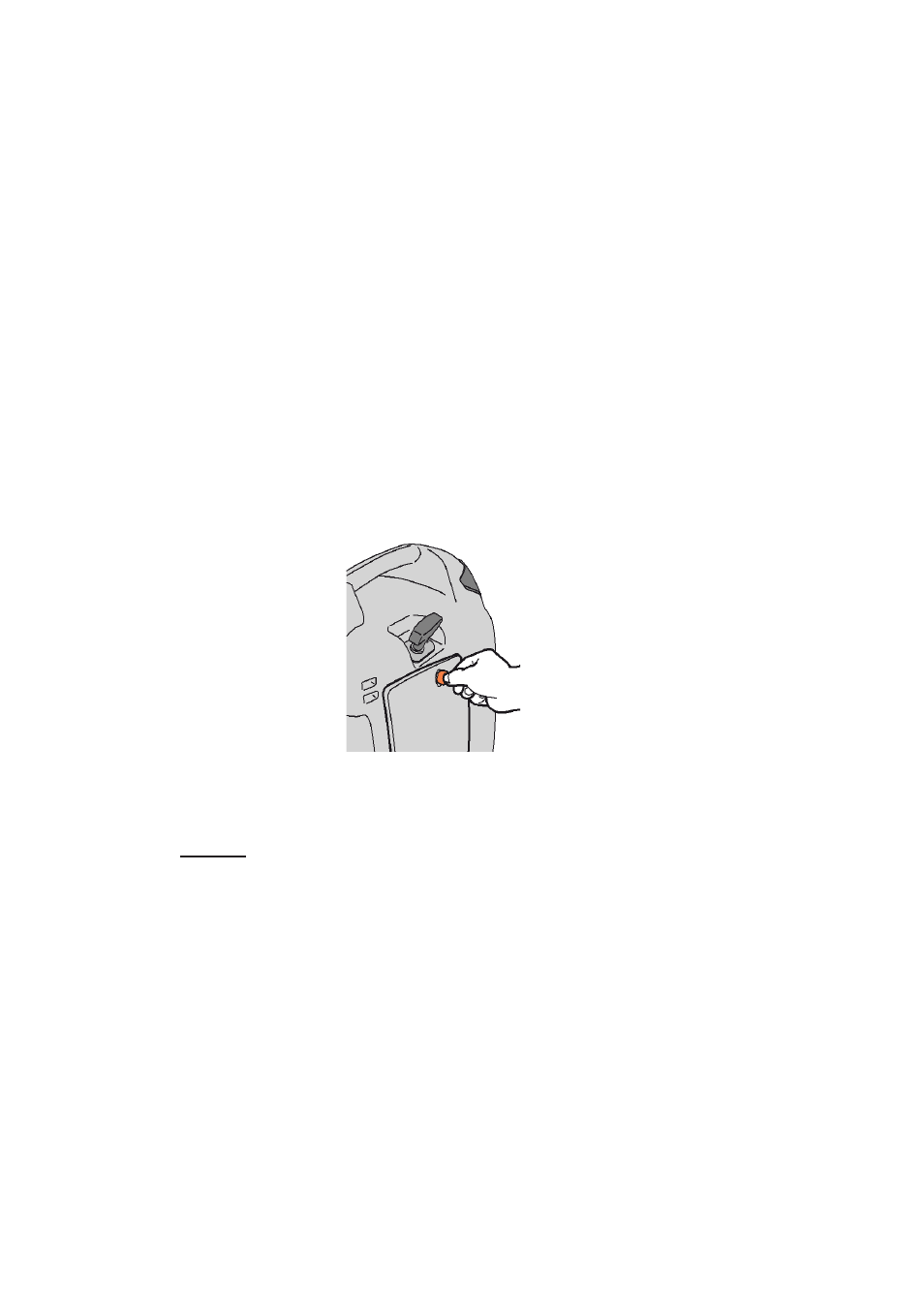
8.4 Opening the side parts
In order to gain access to the following parts for maintenance and repair work, take off the
corresponding side cover by removing the screw with a screwdriver or a coin.
Left side cover:
air ¿ lter, fuel cock, etc.
Right side cover:
oil level gauge, ignition coil, spark plug, hydraulic À uid
¿ lling, etc.