Service (cont.) – Bunn AFPO-3 SL User Manual
Page 20
20
SERVICE (cont.)
VACUUM/SUPPLY PUMP TUBE INSTALLATION
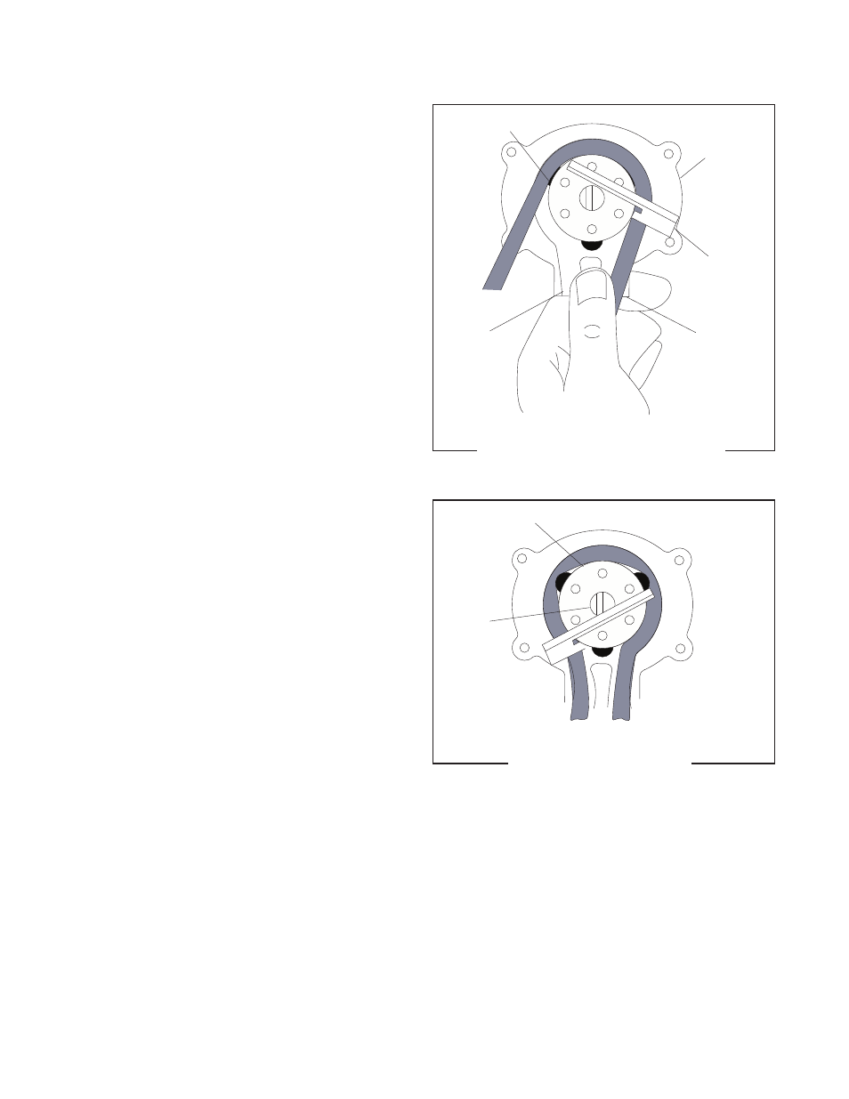
FIG. 24 TUBING START POSITION
P1542
ROLLERS
PUMP
HEAD
TUBING
KEY
ENTRY
PORT
EXIT
PORT
FIG. 25 TUBING LOADED
ROTOR
ROTOR
SHAFT
P1541
2. Separate the two halves of the pump and carefully
remove the tubing from within.
3. Hold the new pump head as shown in Fig. 24, with
rollers in the 2, 6, and 10 o’clock positions.
4. Reinstall tubing in the new pump head by wrap-
ping the tubing around the rollers as shown in Fig.
24.
5. Insert the slot of the tubing key (supplied), as
shown in Fig. 24, on the rotor so the bottom edge
of the key is pressing the tubing into the pump
head cavity as shown in Fig. 25.
6. Hold the tubing and rotor in the pump head and
remove key carefully.
7. Squeeze the pump body and pump heads together
simultaneously until pump body and pump head
are touching on all sides. Be careful not to pinch
the tubing between the pump body and the pump
head.
8. Place the new pump body on the rotor shaft.
9. Replace the four thumbscrews to secure the pump
to the motor assembly. Finger-tighten only.
41093 040408