System setup – Class1 Pump Throttle Electric Cotnrol Series 2 User Manual
Page 11
11
PTEC II
ECU SETUP
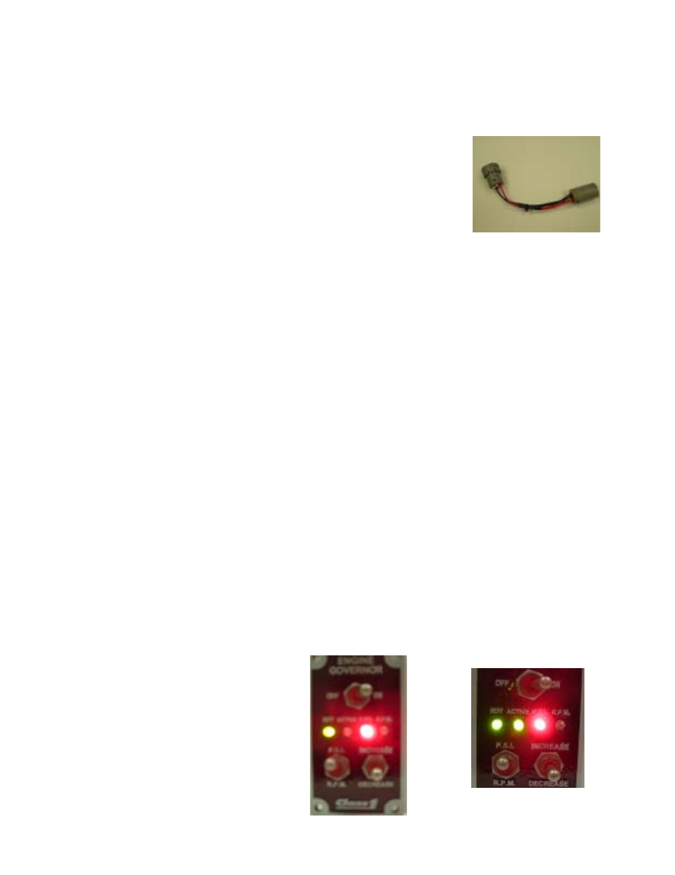
To enter SETUP Mode, place the Diagnostic Connector in-line between the Dash Connector
and the Governor Harness.
PSI and RPM SENSITIVITY
Place the MODE Switch in the PSI position
HOLD the INC/DEC Switch in the INC Position
Turn the GOVERN Switch ON
Release the INC switch after approximately 5 seconds
Use the INC/DEC Switch to adjust the desired setting (count the flashes on the ACTIVE Light)
Typical PSI values range from 6 to 15 with 6 being more sensitive, the default value is 12
Exit by turning off the GOVERN Switch OR
toggle the MODE Switch to the RPM position to set RPM Sensitivity
Use the INC/DEC Switch to adjust RPM Sensitivity
Typical RPM values lie between 1 and 5 with 1 being more sensitive, the default is 2
RAMP SPEED
Place the MODE Switch in the RPM Position
Hole the INC/DEC Switch in the DEC Position
Turn the GOVERN Switch ON
Release DEC after approximately 5 seconds
Use the INC/DEC Switch to adjust the Ramp Speed, the range is 5 to 25 with 5 being the
faster value. Default Ramp Speed is ten (10)
Exit by turning the Govern Switch OFF
FLYWHEEL TEETH
Place the MODE Switch in the PSI Position
HOLD the INC/DEC Switch in the DEC Position
Turn the GOVERN Switch ON
Release the INC switch after approximately 5 seconds
Use the INC/DEC Switch to adjust the flywheel teeth
The ACTIVE Light will flash the setting in increments of ten (10), you must count the number
of toggles until the next 10’s increment is reached, the count should = half the number of
flywheel teeth Flywheel teeth = 134, count should be 67 or 6 flashes and 7 toggles
Exit by turning the Govern Switch OFF
System Setup