System configuration, Figure1 – Class1 Electrical System Manager User Manual
Page 4
4
System Configuration
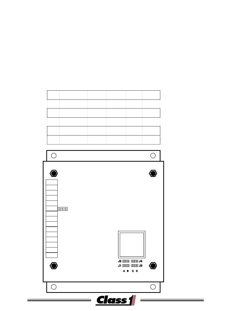
The Electrical System Manager is configured by the use of five jumpers
labeled J1 through J5.
J1 and J5 control battery monitoring (MAIN or MAIN and ISOLATED.)
J2 controls the load reset method (MANUAL or AUTOMATIC.)
J3 controls Load Sequencing (OFF or ON.)
J4 controls when Terminal bar #15 is active (Low Voltage or High Voltage.)
The System Manager cover must be removed to change its operating mode.
J1 through J4 are located at the lower right edge of the circuit board, J5 is
located next to TB #10.
J5
TB#1
TB#9
TB#5
TB#13
TB#3
TB#11
TB#7
TB#15
TB#2
TB#10
TB#6
TB#14
TB#4
TB#12
TB#8
A
B
MODE CONFIGURATION
Figure1
JMP
DESCRIPTION
J1
POSITION
POSITION
POSITION POSITION
A
B
C
D
BATTERIES
MAIN
MAIN/
ISOLATED
J2
J3
J4
J5
RESET
SEQUENCE
TERMINAL #15
FUNCTION
MANUAL
AUTO
OFF
ON
JUMPERS
MAIN
MAIN/
ISOLATED
FAST IDLE
CONTROL
OVER-VOLT
LIGHT
- 4 output tank level (5 pages)
- Digital Aerial Warning Display (6 pages)
- Digital Air Minder (8 pages)
- Digital Clock (1 page)
- Digital Display (35 pages)
- Flowminder 102046 - SSD Digital Flow Meter (9 pages)
- Digital Oxygen Remaining (6 pages)
- Digital Pressure Gauge (6 pages)
- Digital Tank Level Display (5 pages)
- Electronic Fire Commander (8 pages)
- ENFO III (4 pages)
- ENFO IV - 1 page (1 page)
- ENFO IV (10 pages)
- Engine status center (9 pages)
- Engine status OEM menu (3 pages)
- ES-Key-USM (30 pages)
- ESM3 (14 pages)
- Intelli Tank 4 light driver module (9 pages)
- Intelli Tank level display with drip empty (16 pages)
- Intelli-Tank (15 pages)
- Total System Manager (12 pages)
- Total System Manager (19 pages)
- Vernier Throttle for CAT- new (8 pages)
- Vernier Throttle for CAT (12 pages)
- Vernier Throttle for Cummins (9 pages)
- Digital Pressure Service & Calibration (5 pages)
- 109395 - ITL 4LT with 1-wire COM 106296 106299 - 1page (1 page)
- Throttle Information Reference (24 pages)
- ITL Tank Level Driver Module 107451 (9 pages)
- ITL Mini Remote Driver one-page_manual 112648 (1 page)
- Throttle Interface CAT 105216 (8 pages)
- Pump Throttle Electric Cotnrol Series 2 (14 pages)
- 107490 - UNI-Governor 107396 107269 software v 6 00 (38 pages)
- FoamLogix 2.1A & 1.7AHP REV E (96 pages)
- EZFill Foam Refill (46 pages)
- Digital speedometer (4 pages)
- 106759 - ITL 4LT with 1-wire COM 106296 106299 (18 pages)
- 114356 - ITL 4LT with 1-wire and CAN COM 113739 114378 (24 pages)
- 115355 - ITL 4LT with 1-wire and CAN COM 113739 114378 - Page (1 page)
- 117155 - TPG Governor - 117684 EXTERNAL (30 pages)
- 117155 - TPG Governor - 117685 (2 pages)
- 118253 - ITL40 108404-XX - Full (26 pages)
- 118252 - ITL40 118404-XX - Quick Start (1 page)
- 118712 - TPG+ Governor - 118710 (2 pages)