Pinouts, Infinity 6/8h pinout, Infinity supported application 17 – AEM Infinity Supported Applications - Mazda 1986-2002 16B & 20B Rotary User Manual
Page 17
Infinity Supported Application
17
© 2014 AEM Performance Electronics
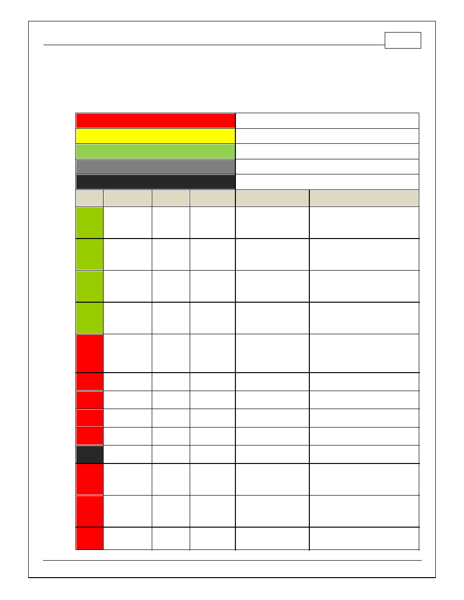
PINOUTS
Infinity 6/8H Pinout
Dedicated
Dedicated and not reconfigurable
Assigned
Assigned but reconfigurable
Available
Available for user setup
Not Applicable
Not used in this configuration
Required
Required for proper function
Infinity
Pin
Hardware
Reference
Mazda FD
Pin
Mazda FD
Function
Infinity Hardware
Specification
Notes
1
LS 4
1-L
A/C Clutch
Lowside switch, 4A max, No
internal f ly back diode.
See Setup Wizard Page "LowSide
Assignment Tables" f or output assignment
and 2D table "LS4_Duty [%]" f or on/of f
activ ation.
2
LS 5
2-B
Tacho
Lowside switch, 4A max with
internal f ly back diode.
Inductiv e load should NOT
hav e f ull time power.
The tachometer can be setup in the wizard
by setting LS5_Freq [Hz] 1-axis table and
the LS5_Duty [%] 2-axis table.
3
LS 6
4-Q
Idle Air Control
Valv e
Lowside switch, 4A max with
internal f ly back diode.
Inductiv e load should NOT
hav e f ull time power.
See Setup Wizard Page "LowSide
Assignment Tables" f or output assignment
and 2D table "LS6_Duty [%]" f or on/of f
activ ation.
4
LS 7
---
---
Lowside switch, 4A max, No
internal f ly back diode.
See Setup Wizard Page "LowSide
Assignment Tables" f or output assignment
and 2D table "LS7_Duty [%]" f or on/of f
activ ation.
5
UEGO1 Heat
---
---
Bosch UEGO controller
Lowside switch f or UEGO heater control.
Connect to pin 4 of Bosch UEGO sensor.
NOTE that pin 3 of the Sensor is heater (+)
and must be power by a f used/switched
12V supply .
6
UEGO1 IA
---
---
Bosch UEGO controller
Trim Current signal. Connect to pin 2 of
Bosch UEGO sensor
7
UEGO1 IP
---
---
Bosch UEGO controller
Pumping Current signal. Connect to pin 6
of Bosch UEGO sensor
8
UEGO1 UN
---
---
Bosch UEGO controller
Nernst Voltage signal. Connect to pin 1 of
Bosch UEGO sensor
9
UEGO1 VM
---
---
Bosch UEGO controller
Virtual Ground signal. Connect to pin 5 of
Bosch UEGO sensor.
10
+12V Perm Power
1-A
Voltage Back Up
Dedicated power
management CPU
Full time battery power. MUST be powered
bef ore the ignition switch input is triggered.
11
Coil 4
1-G
Front Trailing
Coil (sequential)
25 mA max source current
0-5V f alling edge f ire. Do NOT connect
directly to coil primary . Must use an ignitor
or CDI that accepts a f alling edge f ire
signal.
12
Coil 3
---
---
25 mA max source current
0-5V f alling edge f ire. Do NOT connect
directly to coil primary . Must use an ignitor
or CDI that accepts a f alling edge f ire
signal.
13
Coil 2
---
---
25 mA max source current
0-5V f alling edge f ire. Do NOT connect
directly to coil primary . Must use an ignitor