AEM 30-6050 Series 2 Plug & Play EMS User Manual
Page 9
Page 9 of 13
Pin # 00-01 Integra / 98-02 Accord / 99-00 Civic AEM EMS 30-6050
I/O
Availability
B1
Power Source 1
+12V Switched
Both
Dedicated
B2
Power Ground 1
Power Ground
Both
Dedicated
B3
Injector 2
Injector 2
Output
PnP For Injector 2
B4
Injector 3
Injector 3
Output
PnP For Injector 3
B5
Injector 4
Injector 4
Output
PnP For Injector 4
B6
Idle Air Control Valve +
PW 1i
Output
PnP For Idle Control Solenoid
B7
---
High Side Driver 2 Output
Avail, Switched +12v, 1.5A Max
B8
---
Idle #5
Output Avail, Switched Ground, 1.5A Max
B9
Power Source 2
+12V Switched
Both
Dedicated
B10
Power Ground 2
Power Ground
Both
Dedicated
B11
Injector 1
Injector 1
Output
PnP For Injector 1
B12
VTEC solenoid Valve
High Side Driver 1 Output
PnP For VTEC Solenoid
B13
Ignition Control Module
Coil 1
Output
PnP Coil 1, Rising Edge trigger
B14
---
---
---
Not Used
B15
Idle Air Control Valve -
PW1
Output
PnP For Idle Control Solenoid
B16
Intake Air Bypass Solenoid
Injector 8
Output
PnP For IAB Solenoid
B17
---
Idle #6
Output
Avail, Switched +12v, 1.5A Max
B18
---
Idle #7
Output Avail, Switched Ground, 1.5A Max
B19
---
Injector 6
Output Avail, Switched Ground, 1.5A Max
B20
Logic Ground 1
Power Ground
Both
Dedicated
B21
Voltage Back Up
Permanent +12V
Input
PnP For Perm Power
B22
Logic Ground 2
Power Ground
Both
Dedicated
B23
Idle Air Control Valve
PW1
Output
PnP For Idle Control Motor
B24
---
Knock 2
Input
Available, software knock filter
B25
---
Idle #8
Output
Avail, Switched +12v, 1.5A Max
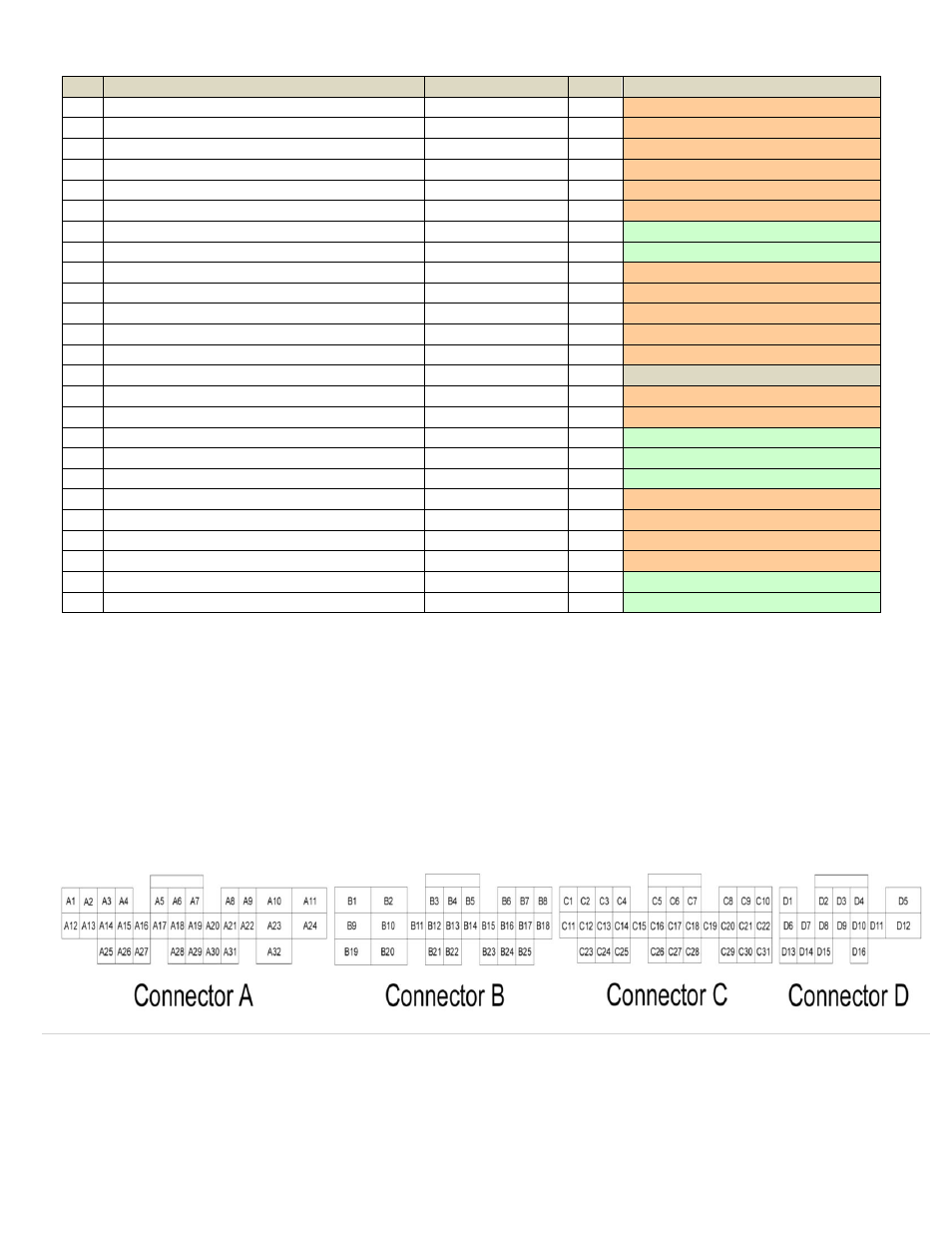
*** Important: Wire View of AEM EMS. Reference diagram below for pin location. ***