AEM 30-4110 Digital Wideband UEGO Gauge User Manual
Page 11
Page 11
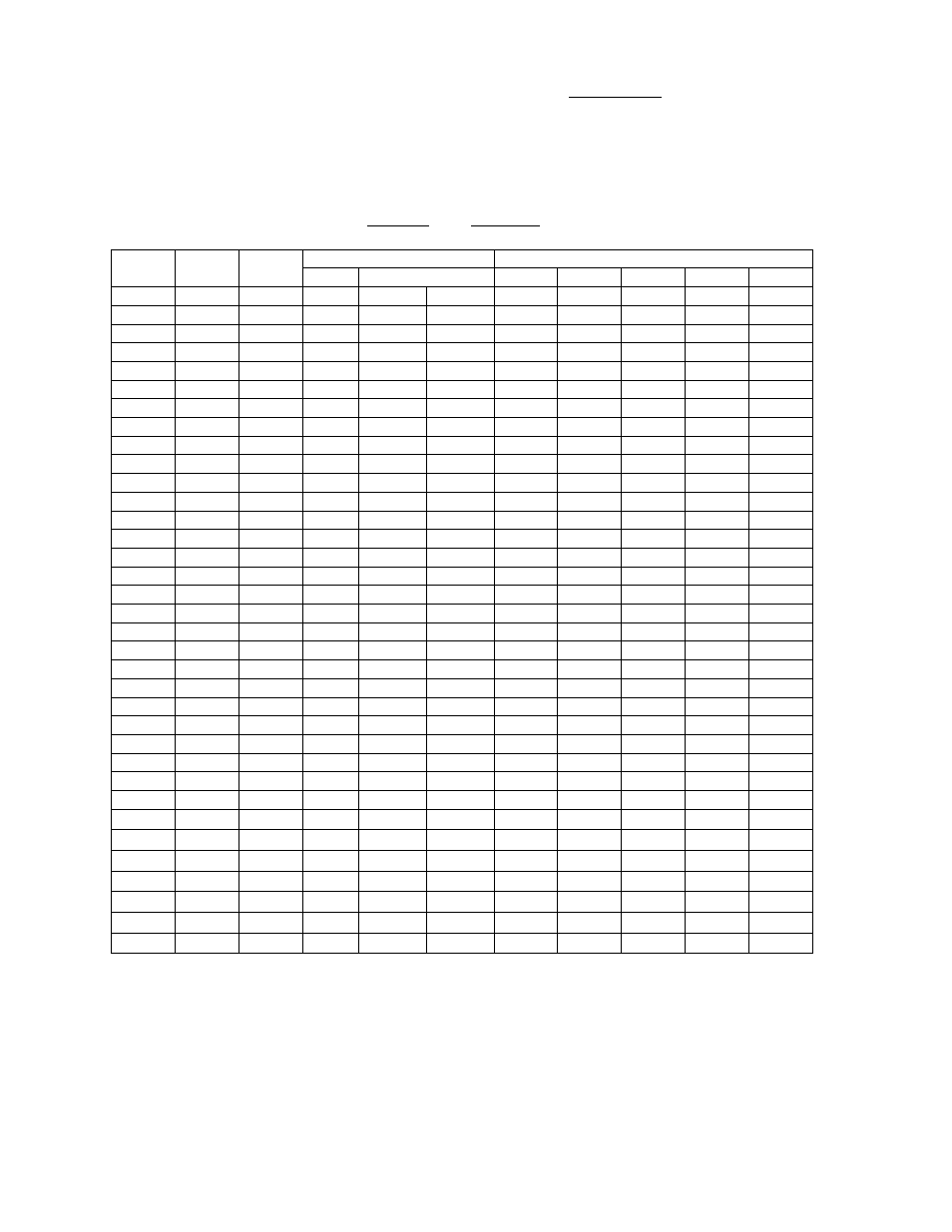
Configuring Calibration Outputs
The AEM default position is (P0). When set to (P0) (Figure 10A), the gauge displays
AFR values. (P1) is the same as (P0), except the gauge displays lambda values. These
settings (P1 and P0) implement a linear calibration with the most useful voltage range
possible (0-5V). The AFR calibration (P2) is linear and similar to (P1) with a smaller
voltage range (1-2V). The AFR calibration (P3) emulates the Autronic Wideband O2
Sensor calibration (0-1V). The AFR calibration (P4) emulates a non-linear Nernst Cell
calibration (0-1V). Refer to the Table 3 and Figure 9 for specific calibration details.
LED
LED Lambda
AFR (Gasoline)
Analog Output Voltage Modes
Number Color
(λ)
AFR
LED
"ON"
Range
P0 P1 P2 P3 P4
LED
1 Green 0.683 10 Rich Rich 0.000 0.000 1.000 0.000 0.905
LED 1 Green
0.700 10.25
Rich
Rich 0.125 0.125 1.025 0.013 0.904
LED 1 Green
0.717
10.5
Rich
Rich 0.250 0.250 1.050 0.025 0.903
LED 1 Green
0.734 10.75
Rich
Rich 0.375 0.375 1.075 0.038 0.902
LED 1 Green
0.751 11.00
Rich
11.125 0.500 0.500 1.100 0.050 0.901
LED 2 Green
0.768 11.25 11.125 11.375 0.625 0.625 1.125 0.063 0.900
LED 3 Green
0.786 11.50 11.375 11.625 0.750 0.750 1.150 0.075 0.890
LED 4 Green
0.803 11.75 11.625 11.875 0.875 0.875 1.175 0.088 0.880
LED 5 Green
0.820 12.00 11.875 12.125 1.000 1.000 1.200 0.100 0.870
LED 6 Green
0.837 12.25 12.125 12.375 1.125 1.125 1.225 0.113 0.860
LED 7 Green
0.854 12.50 12.375 12.625 1.250 1.250 1.250 0.125 0.850
LED 8 Green
0.871 12.75 12.625 12.875 1.375 1.375 1.275 0.138 0.840
LED 9 Green
0.888 13.00 12.875 13.125 1.500 1.500 1.300 0.150 0.830
LED 10 Green
0.905 13.25 13.125 13.375 1.625 1.625 1.325 0.163 0.820
LED 11 Green
0.922 13.50 13.375 13.625 1.750 1.750 1.350 0.175 0.800
LED 12 Yellow 0.939 13.75 13.625 13.875 1.875 1.875 1.375 0.188 0.775
LED 13 Yellow 0.956 14.00 13.875 14.125 2.000 2.000 1.400 0.200 0.750
LED 14 Yellow 0.973 14.25 14.125 14.375 2.125 2.125 1.425 0.213 0.700
LED 15 Yellow 0.990 14.50 14.375 14.625 2.250 2.250 1.450 0.225 0.600
LED 16 Yellow 1.008 14.75 14.625 14.875 2.375 2.375 1.475 0.238 0.410
LED 17 Yellow 1.025 15.00 14.875 15.125 2.500 2.500 1.500 0.250 0.240
LED 18 Yellow 1.042 15.25 15.125 15.375 2.625 2.625 1.525 0.263 0.170
LED 19 Yellow 1.059 15.50 15.375 15.625 2.750 2.750 1.550 0.275 0.137
LED 20 Yellow 1.076 15.75 15.625 15.875 2.875 2.875 1.575 0.288 0.113
LED 21
Red
1.093 16.00 15.875 16.125 3.000 3.000 1.600 0.300 0.100
LED 22
Red
1.110 16.25 16.125 16.375 3.125 3.125 1.625 0.313 0.091
LED 23
Red
1.127 16.50 16.375 16.625 3.250 3.250 1.650 0.325 0.083
LED 24
Red
1.144 16.75 16.625
Lean 3.375 3.375 1.675 0.338 0.077
LED 24
Red
1.161 17.00
Lean
Lean
3.500 3.500 1.700 0.350 0.076
LED 24
Red
1.178 17.25
Lean
Lean
3.625 3.625 1.725 0.363 0.075
LED 24
Red
1.195 17.50
Lean
Lean
3.750 3.750 1.750 0.375 0.074
LED 24
Red
1.212 17.75
Lean
Lean
3.875 3.875 1.775 0.388 0.073
LED 24
Red
1.230 18.00
Lean
Lean
4.000 4.000 1.800 0.400 0.072
LED 24
Red
1.247 18.25
Lean
Lean
4.125 4.125 1.825 0.413 0.071
LED 24
Red
1.264 18.50
Lean
Lean
4.250 4.250 1.850 0.425 0.070
Table 3. Calibration table of available outputs