Install aemnet adapter harness – AEM 30-3432 Series 2 AEMnet Adapter User Manual
Page 5
Page 5
INSTALL AEMnet ADAPTER HARNESS
4. Table 2 below lists the corresponding CAN1L and CAN1H pin locations for each Series 2
EMS.
CAN1L (Green wire)
CAN1H (White wire)
EMS
Adapter p/n
LOCATION
LOCATION
30-6030
30-3430
C22
C21
30-6050
30-3432
D14
D10
30-6051
30-3432
D14
D10
30-6052
30-3432
D14
D10
30-6053
30-3432
D14
D10
30-6060
30-3432
C28
C29
30-6310
30-3431
77
87
30-6311
30-3431
57/77
67/87
30-6320
30-3435
33
13
Table 2: CAN1L and CAN1H pin locations
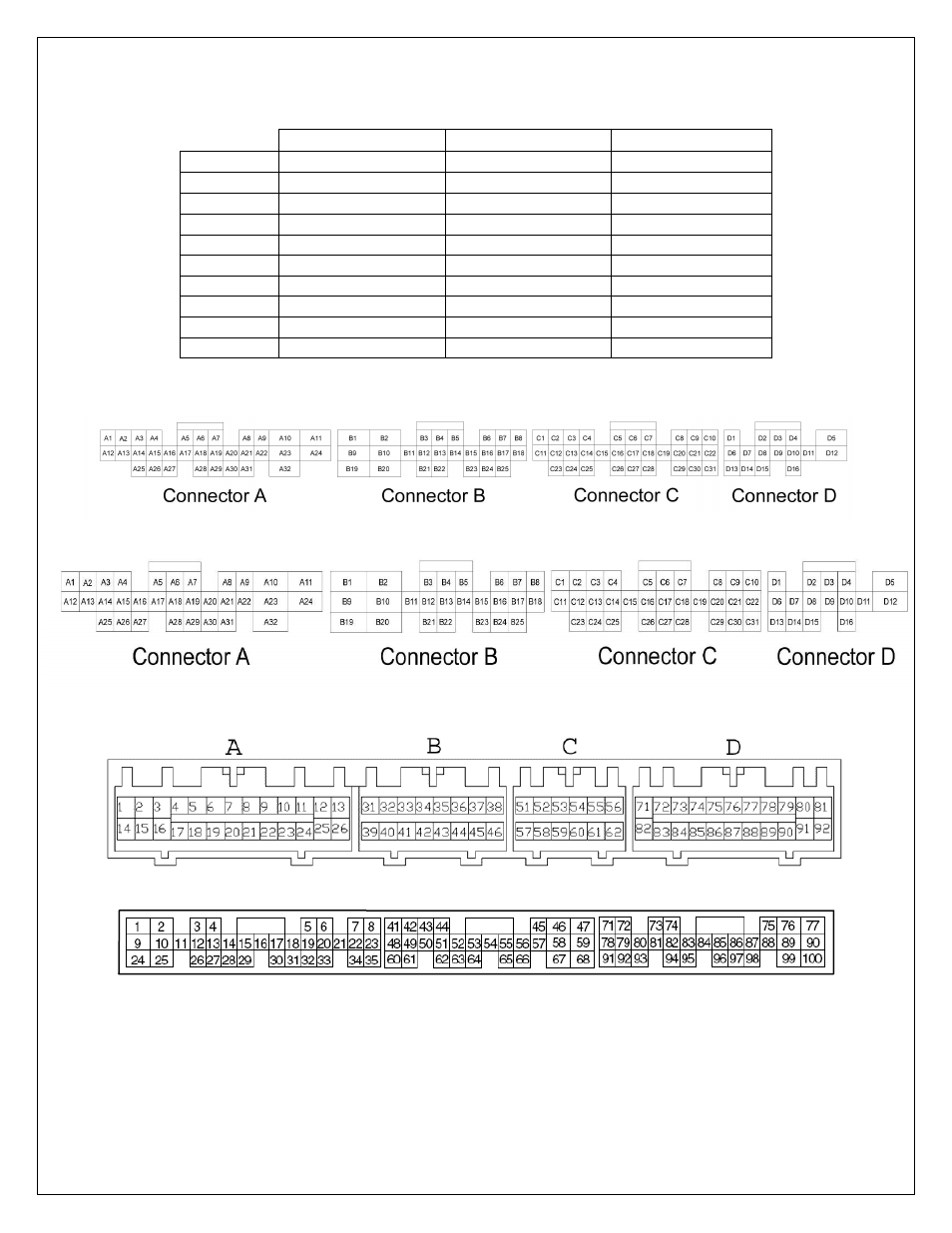
Figures 7, 8, 9, and 10 below show the connectors for each Series 2 EMS.
Figure 7: Wire-side view of pinout for 6030
Figure 8: Wire-side view of pinout for 6050, 6051, 6052, 6053, and 6060 EMS
Figure 9: Wire-side view of pinout for 6310 and 6311 EMS
Figure 10: Wire-side view of Pinout for 6320 EMS
- 30-71XX Infinity EMS Quick Start Guide (53 pages)
- 23-800BK Tru-Time Adjustable Cam Gear (7 pages)
- 23-801BK Tru-Time Adjustable Cam Gear (11 pages)
- 23-830BK Tru-Time Adjustable Cam Gear (8 pages)
- 23-831BK Tru-Time Adjustable Cam Gear (7 pages)
- 23-850BK Tru-Time Adjustable Cam Gear (6 pages)
- 23-851BK Tru-Time Adjustable Cam Gear (7 pages)
- 25-100BK High Volume Fuel Rail (5 pages)
- 25-104BK High Volume Fuel Rail (5 pages)
- 25-108BK High Volume Fuel Rail (7 pages)
- 25-109BK High Volume Fuel Rail (6 pages)
- 25-111BK High Volume Fuel Rail (6 pages)
- 25-130BK High Volume Fuel Rail (6 pages)
- 25-131BK High Volume Fuel Rail (4 pages)
- 25-200BK Honda/Acura High Volume Fuel Filter (3 pages)
- 25-201BK Universal High Volume Fuel Filter (4 pages)
- 25-300BK Honda/Acura Adjustable Fuel Pressure Regualtor (9 pages)
- 25-302BK Universal Adjustable Fuel Pressure Regualtor (5 pages)
- 25-391 High Volume Fuel Rail AN Adapter Kit (5 pages)
- 25-392 Honda/Acura Adjustable Fuel Pressure Regualtor (4 pages)
- 30-1910 Universal Fuel Ignition Controller 6 Channel (33 pages)
- 30-1930 Universal Fuel Ignition Controller 8 Channel (34 pages)
- 30-1960 Plug & Play Fuel Ignition Controller 6 Channel (5 pages)
- 30-2010 Air Temp Sensor Kit (2 pages)
- 30-2011 Water Temp Sensor Kit (2 pages)
- 30-2012 Water Temp Sensor Kit (2 pages)
- 30-2020 Bosch Injector Plug Kit 4 Pack (2 pages)
- 30-2050 RTD Temperature Sensor Kit (1 page)
- 30-2056 Universal 12 Position Trim Pot (1 page)
- 30-2065 K-Type Closed Tip Thermocouple Sensor Kit (2 pages)
- 30-2066 K-Type Closed Tip Thermocouple 10 Wiring Extension Kit (2 pages)
- 30-2067 X-WiFi K-Type Closed Tip Thermocouple Kit (2 pages)
- 30-2130-XXX Stainless Steel Pressure Sensor (2 pages)
- 30-2131-XXX Brass Pressure Sensor (2 pages)
- 30-2204 K-Type Thermocouple Amplifier 4 Channel (6 pages)
- 30-2310 Inline Wideband UEGO Controller (8 pages)
- 30-2067 X-WiFi Wideband UEGO & EGT Controller (14 pages)
- 30-2340 4-Channel Wideband UEGO AFR Controller (30 pages)
- 30-2340-N 4-Channel Wideband UEGO AFR Controller - For use with Nascar McLaren ECU (28 pages)
- 30-2355-XXX No-Weld O2 Sensor Mount (4 pages)
- 30-2400 Boost Control Solenoid Kit (2 pages)
- 30-2500 AQ-1 Data Logging System (22 pages)
- 30-2710 Peak & Hold Injector Driver 10 Channel (5 pages)
- 30-2840 4 Channel Coil Driver (2 pages)
- 30-2841 1 Channel Coil Driver (4 pages)