AEM 30-3432 Series 2 AEMnet Adapter User Manual
Page 2
Page 2
AEMnet CONNECTORS
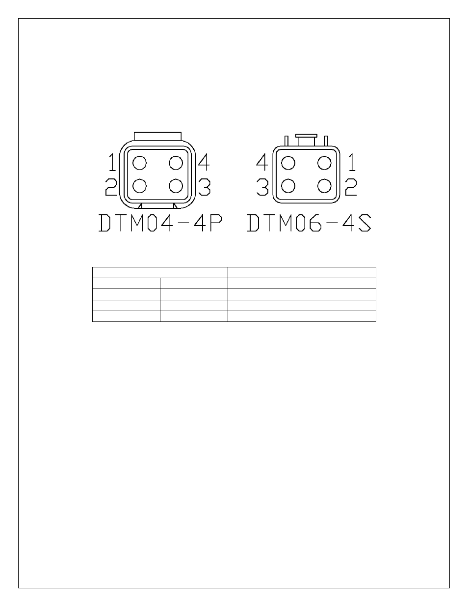
The AEMnet has four wires, two are for communication (white pin 1 and green pin 2) and two are for
powering (red pin 3 and black pin 4) certain AEMnet devices. Only the two communication wires
(white pin 1 and green pin 2) are needed for the Series 2 EMS to send/receive data as the EMS is not
powered by AEMnet. The red and black wires will need to be connected when using the Series 2
EMS with devices that are powered by AEMnet such as the Dyno-Shaft (see individual instructions for
details). The AEMnet connectors are shown below in figure 1. See table 1 for the AEMnet connection
pinout.
Figure 1: AEMnet connectors, wire entry view
AEMnet Connector
Series 2 EMS Connector
Pin 1
White
CAN1H
Pin 2
Green
CAN1L
Pin 3
Red
AEMnet Power (switched 12 volts)
Pin 4
Black
AEMnet Ground
Table 1: AEMnet connector pinout