Epm wiring - connector pinout, Mounting/dimensions – AEM 30-3250 Engine Position Module User Manual
Page 3
Page 3
10-3250 for 30-3250 EPM Puck RevA 022212
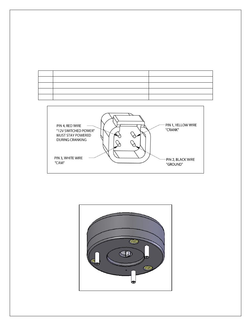
EPM WIRING - CONNECTOR PINOUT
1. The EPM has a short cable with a 4 Pin Deutsch connector, supplied with the
EPM is the mating connector housing with 5 crimp terminals. The connector
pinouts are shown in figure 1.
2. The EPM outputs a 12V square wave, 24 crank signals and 1 short pulse cam
signal every 360 degrees.
Pin
Description
Wire Color
1
CRANK
Yellow
2
GROUND
Black
3
CAM
White
4
12V Switched Powered During Cranking
Red
MOUNTING/DIMENSIONS
Figure 2. Bottom View of EPM
Figure 1. 4 Pin EPM Deutsch Connector, Wire Entry View
See also other documents in the category AEM For the car:
- 30-71XX Infinity EMS Quick Start Guide (53 pages)
- 23-800BK Tru-Time Adjustable Cam Gear (7 pages)
- 23-801BK Tru-Time Adjustable Cam Gear (11 pages)
- 23-830BK Tru-Time Adjustable Cam Gear (8 pages)
- 23-831BK Tru-Time Adjustable Cam Gear (7 pages)
- 23-850BK Tru-Time Adjustable Cam Gear (6 pages)
- 23-851BK Tru-Time Adjustable Cam Gear (7 pages)
- 25-100BK High Volume Fuel Rail (5 pages)
- 25-104BK High Volume Fuel Rail (5 pages)
- 25-108BK High Volume Fuel Rail (7 pages)
- 25-109BK High Volume Fuel Rail (6 pages)
- 25-111BK High Volume Fuel Rail (6 pages)
- 25-130BK High Volume Fuel Rail (6 pages)
- 25-131BK High Volume Fuel Rail (4 pages)
- 25-200BK Honda/Acura High Volume Fuel Filter (3 pages)
- 25-201BK Universal High Volume Fuel Filter (4 pages)
- 25-300BK Honda/Acura Adjustable Fuel Pressure Regualtor (9 pages)
- 25-302BK Universal Adjustable Fuel Pressure Regualtor (5 pages)
- 25-391 High Volume Fuel Rail AN Adapter Kit (5 pages)
- 25-392 Honda/Acura Adjustable Fuel Pressure Regualtor (4 pages)
- 30-1910 Universal Fuel Ignition Controller 6 Channel (33 pages)
- 30-1930 Universal Fuel Ignition Controller 8 Channel (34 pages)
- 30-1960 Plug & Play Fuel Ignition Controller 6 Channel (5 pages)
- 30-2010 Air Temp Sensor Kit (2 pages)
- 30-2011 Water Temp Sensor Kit (2 pages)
- 30-2012 Water Temp Sensor Kit (2 pages)
- 30-2020 Bosch Injector Plug Kit 4 Pack (2 pages)
- 30-2050 RTD Temperature Sensor Kit (1 page)
- 30-2056 Universal 12 Position Trim Pot (1 page)
- 30-2065 K-Type Closed Tip Thermocouple Sensor Kit (2 pages)
- 30-2066 K-Type Closed Tip Thermocouple 10 Wiring Extension Kit (2 pages)
- 30-2067 X-WiFi K-Type Closed Tip Thermocouple Kit (2 pages)
- 30-2130-XXX Stainless Steel Pressure Sensor (2 pages)
- 30-2131-XXX Brass Pressure Sensor (2 pages)
- 30-2204 K-Type Thermocouple Amplifier 4 Channel (6 pages)
- 30-2310 Inline Wideband UEGO Controller (8 pages)
- 30-2067 X-WiFi Wideband UEGO & EGT Controller (14 pages)
- 30-2340 4-Channel Wideband UEGO AFR Controller (30 pages)
- 30-2340-N 4-Channel Wideband UEGO AFR Controller - For use with Nascar McLaren ECU (28 pages)
- 30-2355-XXX No-Weld O2 Sensor Mount (4 pages)
- 30-2400 Boost Control Solenoid Kit (2 pages)
- 30-2500 AQ-1 Data Logging System (22 pages)
- 30-2710 Peak & Hold Injector Driver 10 Channel (5 pages)
- 30-2840 4 Channel Coil Driver (2 pages)
- 30-2841 1 Channel Coil Driver (4 pages)