Defi ADVANCE Control Unit (DF07701 Manufactured in and before December, 2011) User Manual
Page 8
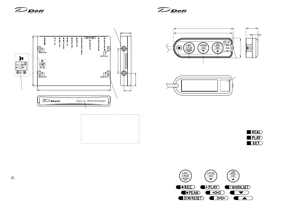
5 -2. Part Names & Dimensions of Control Unit in mm(inches)
●
Connectors for wires
① Switch unit(white)
② Speed&Tachometer signal wire(blue)
③ Exhaust temp sensor wire(black)
④ Water temp sensor wire(pink)
⑤ Oil temp sensor wire(red)
⑥ Fuel press sensor wire(red)
⑦ Oil press sensor wire(white)
⑧ Turbo/In-Mani sensor wire(light blue)
⑨ Power source wire(beige)
⑩ Meter wire(white) ⑪ Meter wire(white)
Meter wires can be connected to both ⑩ and ⑪ . To protect against short-circuit
between two terminals, the convex connector is inserted into the concave con-
nector ⑪ at the factory prior to shipment. If You don't use ⑪ , do not remove
the convex connector. When using ⑪ , please pull out the convex connector
by pressing the lock, and then connect the meter wire.
153.2(6.03")
DC source(wiring check) LED (blue)
Slots for screw
nut (4 places)
Screw holes(4 places)
104(4.1")
51(2")
26.3(1.04")
22(2.05")
15(0.59")
①
② ③④ ⑤ ⑥ ⑦ ⑧
⑨
⑩ ⑪
●
Dip switch 1&2
1: Warning buzzer sounds ON/OFF
change
2: Opening・Closing modes
selection(A/B)
Dip switch
5 -3. Part Names & Dimensions of Switch unit in mm(inches)
●
Buttons and slide switch
Operation of gauges is handled by 3 buttons and 1 slide switch. By sliding the
switch position, the functions of buttons change.
●
Slide switch
In this manual, positions of the slide switch are illustrated as follows:
REAL(upper): for Real mode operation
U
PLAY(middle): for operation to replay recorded data
M
SET(lower): for operation to set up
L
●
Buttons
Each button has three marks(upper, middle, and lower position) in accordance
with positions of slide switch. In this manual, each button is illustrated as fol-
lows:
Left button:
L
or
L
or
L
from the top
Middle button:
M
or
M
or
M
from the top
Right button:
R
or
R
or
R
from the top
Left
Middle
Right
80(3.15")
78.4(3.09")
26.2(1.03")
16(0.63")
Differential pres-
sure LED(blue)
●
Backside of switch unit
Slide switch
(REAL/PLAY/SET from the top)
Left button
Middle button
Lot No. label
Do not peel the labels
sticked on the the product
and warranty card.
Right button
Applying position of
double-sided tape
7(0.28")
50
51