Defi Racer Gauge 80 tachometer User Manual
Manual, Safety warning 【please read carefully, Lineup
Before handling (for installation personnel)
Properties for safety warning
Indicates attention needs to be paid. (Including warnings)
Indicates restricted actions. (PROHIBITED actions)
Indicates actions that need to be carried out. (MUST actions)
Prohibited
Must
Thank you very much for purchasing our product.
This product is an additional product for providing information to automobile users about engine conditions
and other important factors. Before installing and using the product, please read this manual and the
warranty card thoroughly. All sections are for customers and installation personnels. After installation,
please keep this manual and the warranty card for future reference. In the event that this product (or the
vehicle in which it is installed) is lent to or transferred to another person, please be sure this operation
manual and warranty card accompany the product.
Defi will not be held responsible for accidents or damages related to installation of this product.
When installing and operating this product, be sure to read the cautionary items in the operation manual for
the vehicle in which this product will be installed in addition to the manual of this product. Please obtain a
full understanding of the cautionary items and use the product accordingly. Before using the product,
please confirm all the components are included in the package.
Safety Warning
【Please read carefully.】
In this manual, the degree of hazard arising from actions such as improper operation is separated into the 3
levels "Danger," "Warning," and "Caution." In addition, instructions that must be followed for safe and
proper use of this product as well as practices that must be maintained are marked with a "Confirmation"
heading. Please read and become familiar with these sections.
Caution
Warning
Confirmation
Danger
Indicates the imminent dangerous situation of death or serious injury if the product is
mishandled.
Indicates the possibility of death or serious injury if the product is mishandled.
Indicates a conceivable source of personal injury or damage to equipment if the product
is improperly operated.
Indicates an instruction that must be performed or practice that must be maintained.
Warning
disassemble/
modify
Caution
24V
Carefully consider the installation location and driver's operation of the product before installation. Do
not install the product where it interrupts driving and the safety deices of vehicle such as the airbag
system. Be sure not to install the unit where it could fall. Improper installation or operation could
cause the product to fall and damage the vehicle or cause serious danger by impeding driving.
Do not disassemble or modify this product. Such actions will not only void the warranty but also
damage or destroy the product.
Do not perform installation of this product immediately after the engine has been switched off. The
engine and exhaust system are extremely hot at this time and can cause burns if touched.
Ensure that the wiring of this product does not have an adverse impact on the other wiring of the vehicle. Any
controlling devices or other electronic components of the vehicle could be damaged.
Discontinue use of this product if the product doesn't operate or operates improperly. Continued use while the
condition exists could result in an accident or fire.
Please keep children and infants away from the installation area. Children may swallow small parts or be injured in
other ways.
Do not install this product in the area where safety equipment such as airbags are mounted. This may cause more
injuries in the event of an accident.
Danger
Ensure that the vehicle will remain stationary and turn off the engine before installing this product. Failure to do so
could result in a fire, and could make the vehicle move during installation.
Remove the key from the ignition and disconnect the negative (-) battery terminal prior to installation of this product.
Failure to do so could result in a fire caused by an electrical short circuit.
Take care not to install this product in a way that interferes with safety equipment such as seat belts and air bag
systems or vehicle operation equipment such as engine controls, steering wheel or brake systems. Interference
with normal operation of the vehicle can result in an accident or fire.
Solder or use a solderless connector for wiring connections and make sure connections are insulated. In areas
where there could be tension or sudden impacts on the wiring, safeguard the wiring with corrugated tubing or other
shock absorbent material. Accidental shorts can cause fires.
When wiring power supply wire, to avoid the risk of electrical shock or fire, be sure to confirm that there is no
disconnection or breakage of wire. Poor connection can result in short-circuit, electrical shock, fire, or other hazards.
The ignition-switched +12V(IGN) line must be connected to the vehicle's ignition-switched wire with a fuse of 30A or
less. High-capacity fuse(more than 30A) will not blowout even with an abnormal current flow and may cause fire.
Use the fuse of regulated capacity when the fuse of the power wire is changed. Using a fuse that exceeds regulated
capacity may cause fire and may affect the accuracy.
Do not install the product at the wet places. It may result in a fire caused by an electrical short circuit.
This product is designed for use on 12V vehicles. Do not install this product on vehicles with 24V systems.
Insulate any unused wires. If any wires or connectors loosen during installation, please make sure
they are correctly reattached.
Do not drop any of the components of this product. It may result in damage to the product.
Do not apply excessive force on switches/terminals. It may result in damage to the product.
Do not use wires other than the provided wires.
Do not attach wires on the body of the vehicle or engine parts as this may result in damage to the product.
Install wires away from ignition and also radio signal frequency interference as this could cause the gauges to
malfunction.
Do not place wires near the engine, exhaust pipe or turbine. It may result in damage or fusion of wires.
Make sure the waterproof processing is done when diverging wires in the engine compartment.
Wear gloves to avoid burns when soldering and cuts when installing wires, sharp edges of parts.
When using sunshade, put sunshade between products and windshield to avoid direct sun exposure .
Use the dried soft cloth for cleanup. Do not use the cleaner except for the neutral detergent. It result in the trouble.
Do not pull the wires out of connectors forcefully. The connectors may be broken and the wires
may be cut. When pulling out the wires, press the lock firmly and unclip the locks of connectors.
Do not install gauges into the passenger side or center of the dashboard. It doesn't meet
vehicle safety standards.
http://www.defi-shop.com/
'11.10-1
Confirmation
Be sure to follow all instructions in this manual to ensure safe installation and operation of the product.
When the negative (-) battery terminal is disconnected, equipment such as clocks and audio components having
internal memory may lose their memory data. Follow the operation manual of each component to reset data after
installation of this product.
After installation is complete, return this operation manual, warranty card, and the package to the customer along
with the warranty.
The gauge pointer may not be in the proper position when you purchase the product. Normal function will resume
when power is connected.
Please confirm with the maintenance book on the car that the manufacturer issued when installing and detaching
genuine parts.
Before tapping wires, check the voltage of the existing wire. After tapping the wire, check the voltage of the tapped
wire again to confirm whether you have tapped into the proper place.
If car navigation system or car television is installed in vehicle, gauges and wires of this product need to be kept as
far away as possible from the wiring and installing positions of car navigation system or car television. Failure to do
so may result in interference of television display.
On no event will Nippon Seiki Co., Ltd. be liable to you for any damages or losses of genuine parts for your vehicle
while installing.
Confirmation
About Installation and Operation(for customer and installation personnel)
Warning
On no event will Nippon Seiki Co., Ltd. be liable to you for any damages arising out of the use or inability to use the
product, even if Nippon Seiki Co., Ltd. has been advised of the possibility of such damage.
Do not pull the wires out of connectors forcefully. The connectors may be broken and
the wires may be cut. When pulling out the wires, press the lock firmly and unclip the
locks of connectors.
Caution
This product cannot be linked to either the ADVANCE System or the Defi-Link System.
The information displayed on this product are for reference purposes only. Please drive according to the indication
of vehicle's originally equipped instruments.
This product uses high luminance LEDs. When several gauges are lined up, there might be color difference in the
LED production tolerance, but it is not malfunction.
This product can be used only on 1, 2, 3, 4, 5, 6, and 8 cylinder vehicles with 4 cycle engine. Refer to the Product
Specifications. Engine revolution signal of diesel vehicles cannot be displayed.
Please check the installed product regularly. Durability might deteriorate according to use conditions, etc.
Please have this product installed by the retail store or dealer where it was purchased. Installation by the customer
will void the warranty.
Do not disassemble or modify this product. Such actions will not only void the warranty but also damage or destroy the product.
In order to ensure safe driving, check the information on the gauge only for short periods of time. Looking at the
display for long periods of time could distract adequate attention from the road and result in an accident.
Discontinue use of this product if the gauge doesn't operate, water gets into the unit, or smoke or a strange odor
comes from the unit. If such a condition occurs, contact the sales outlet or installation personnel as soon as
possible. Continued use while the condition exists could result in an accident or fire.
Do not operate during driving.
Fix the switch unit and other parts tightly to the vehicle to avoid that children swallow those.
Manual
Racer Gauge Tachometer Φ80
DF12001∼DF12003, DF12101∼DF12103
DF12001
DF12101
DF12002
DF12102
DF12003
DF12103
Display range
0
∼9000RPM
0
∼11000RPM
Blue
Illumination color of gauge and switch
Red
White
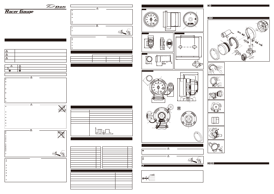
STEP3
Installing gauge
STEP3
Installing gauge
Install the gauge as shown in the following procedures and figures.
①Gauge
⑰Buffer
②Switch unit
③Regular Position Bezel
④Back case
⑱Double sided tape
⑤Mounting band
⑥Mounting rubber
⑧Indicator
⑪Mounting bracket
⑫Attachment
for switch unit
⑬M6 bolt
⑭Spring lock washer
⑮Washer
⑯Spacer
⑲Tapping screw
⑱Double sided tape
【Figure1】 Gauge assembly
1) Attach the buffer around the gauge.
【Figure1】
※Do not touch on the front face of the gauge so as not to put fingerprints.
2) Fit the mounting rubber inside of the mounting band.
【Figure2】
3) Fix the mounting band to the mounting bracket temporarily with the spacer, bolts,
washers, and spring lock washers. Tighten bolts loosely by hands. Do not use a
hexagonal wrench (Allen key) at this stage.
【Figure3】
4) Insert the switch unit into the attachment for switch unit.
【Figure1】
※If the switch unit is fixed to another place other than the gauge, do not use the
attachment for switch unit.
5) Fit the attachment for switch unit and indicator into the mounting band. And then fit
the gauge into the mounting band. Locate the switch unit and the indicator roughly
at this stage. The switch unit and the indicator can be positioned in the range which
they do not touch the mounting bracket and bolts.
【Figure4】
【Figure5】
※Do not take hands off from the gauge so as the gauge does not fall down.
※If the switch unit is fixed to another place other than the gauge, do not fix/use the
attachment for switch unit to the mounting band.
6) Identify the position of the mounting bracket with the gauge fitted into the mounting
band. Mark the shape of the mounting bracket and the position of the screw holes.
The figure printed on the package can be used to position the screw holes.
※To check that there is enough space for installation, identify the gauge position
with the gauge, switch unit, and indicator fitted into the mounting band.
※When setting the gauge angle, take care not to scratch by hitting the gauge to the
mounting bracket.
7) Disassemble the mounting band from the mounting bracket, and disassemble the
gauge, attachment for switch unit, and indicator from the mounting band.
8) Attach double sided tapes on the bottom of the mounting bracket.
【Figure1】
【Figure6】
9) Fix the mounting bracket on the gauge installing position by using the tapping screws.
10) Fit the attachment for switch unit, indicator, and gauge into the mounting band again.
Take notice that the angle of the switch unit and the indicator cannot be changed
while the bolts are fastened.
※If the switch unit is fixed to another place other than the gauge, do not fix/use the
attachment for switch unit to the mounting band.
11) Attach the double sided tape on the back side of the gauge.
【Figure1】
【Figure6】
12) Pass the indicator wire and switch unit wire through the holes of the back case from
the outside. Connect the indicator wire to the connector on the gauge. Refer to part
names section.
【Figure7】
【Assembling example】
13) Put the back case on the gauge. Position the hole for the power supply & tachometer
signal wire to the gauge connector for it. Refer to part names section. The indicator
wire can be stored in the back space in the back case.
【Assembling example】
14) Connect the switch unit wire to the connector on the back side of the gauge. The
indicator wire can be stored in the storage space in the back case neatly.
【Assembling example】
15) Connect the power supply & tachometer signal wire to the connector on the back
side of the gauge.
【Assembling example】
16) Fit the mounting band with the gauge in the mounting bracket by using a spacer,
bolts, washer, and spring lock washer.
※Depending on the installing space, it may difficult to fit the gauge. Do not pull
wires forcefully and take notice not to hit the vehicle by parts.
17) Fasten the bolts with a hexagonal wrench (Allen key) firmly.
【Figure8】
18) Fit the regular position bezel onto the gauge with setting the ▼ mark at the position
you like.
【Figure2】Fitting rubber in band
【Figure3】Fixing band to bracket
【Figure5】Range of fitting of switch unit
and indicator
【Figure6】How to use double sided tape
【Figure4】Fitting indicator, attachment
for switch unit, and gauge in band
【Figure8】Fasten bolts with hexagonal
wrench
【Figure7】Connect indicator wire
For bottom of bracket
For inner side of back case
Pass wires
through
holes from
back side
STEP4
Final check and setup
STEP4
Final check and setup
1) Make sure the gauge is fixed on the installing position firmly. Then turn the vehicle engine on and off and check the
movement of the pointer, illumination of the gauge, and engine speed signal input.
※Make sure there are no tools on the vehicle floor and that the vehicle surrounding is safe before turning on the engine.
2) Go on to the operation section and set up the number of cylinders, and so on. Give this manual to the customer if
he/she sets up by himself/herself.
front
front
back
back
Dimensions in mm(inches) and part names
Main Features
(for customer)
Lineup
(for customer)
●Stepping motor "STS26A"
Maximum angle of deflective 270° (full sweep) is controlled by the microcomputer up to 4600 division(0.057° each) to
provide high precision in the accuracy of information generated.
The stepping motor is sufficient for quick response of all sorts of professional motorsports.
●LED illumination
The gauge dial is invisible while the ignition switch is off. Once the ignition switch is turned on, a clear display appears
by colored LED illumination.
The gauge dial illumination and the red emitting needle pointer provide high visibility.
●Opening and closing modes
The gauge dial and the needle pointer performs opening and closing modes interlocked with turning ON/OFF of the ignition.
●Adjustable brightness
There are 5 stages of brightness for the daytime and 6 stages for the nighttime. The brightness can be
decreased/increased with the vehicle lights switched on/off.
●Dual warnings of light and buzzer
Two customer-defined warning RPMs can be set. When the RPMs are exceeded, the warning LED blinks/lights up
and the warning buzzer sounds.
●Exclusive large-sized indicator
The exclusive large-sized indicator which lights in green and red enhances the visibility of warnings in addition to the
warning LED in the gauge.
●Peak memory function
The maximum RPM during driving can be stored and checked later.
●Detachable switch unit
The large-sized switch unit with light is fixable on the gauge and is also detachable.
●Exclusive mounting band and back case
The gauge is clinched by using the exclusive mounting band and back case. Wires can be stored in the back case neatly.
Product Specifications(for customer and installation personnel)
Power Supply Voltage
Current Consumption
Operational Temperature Range
Storage Temperature Range
Applicable Number of Cylinders
Applicable Engine Speed Pulse
DC10V to 15V
(For 12V vehicles)
+B (red) line
IGN (orange) line
ILM (white) line
−20 to +60℃, −4 to +140°F (under 80% relative humidity)
−30 to +80℃, −22 to +176°F (under 80% relative humidity)
1
・2・3・4・5・6・8
The wave form of the engine speed signal should meet the requirements
of the following graph.
MAX 0.4A
(Dark current 0mA)
MAX 0.4A
MAX 2mA
Engine speed input (blue wire)
V1) 4.0V and above
V2) 0
∼1.5V
Time
V1
V2
Volt
4.0V and
above
0
∼1.5V
Part Name
Quantity
①Gauge
②Switch unit(wire 45cm, 1.48ft)
③Regular Position Bezel
④Back case
⑤Mounting band
⑥Mounting rubber
⑦Power supply & tachometer signal wire 2.2m, 7.2ft
⑧Indicator(wire 20cm, 7.8in)
⑨Operation manual
⑩Warranty card
1
1
1
1
1
1
1
1
1
1
Part Name
Quantity
1
1
2
2
2
1
1
1
2
5
⑪Mounting bracket
⑫Attachment for switch unit
⑬M6 bolt
⑭Spring lock washer
⑮Washer
⑯Spacer
⑰Buffer
⑱Double sided tape
⑲Tapping screw
⑳Solderless connector
Part Name
Φ80(3 1/8") Mounting band set
(Mounting band x1, Mounting rubber x1)
Part Number
PDF07103G
Φ80(3 1/8") Back case set
(Back case x1, Buffer x1)
PDF07101G
Power supply & tachometer signal wire
PDF12010H
Φ80(3 1/8") Mounting bracket set
(Mounting bracket x1、M6 bolt x2,
Spring lock washer x2, Washer x2, Spacer x1, Tapping screw x2
)
PDF07104G
Φ80(3 1/8") Regular Position Bezel
PDF07105G
Fuse for Power supply wire(1A) 2pcs
PDF07113G
The following parts are included with this product. Confirm that all parts are present before installing the product. In
addition, these parts are sold separately for part replacement. Contact your retailer for further information.
NOTE: Japanese operation manual and wiring manual are included other than the parts listed below. They are effective
only in Japan.
Parts List
(for customer and installation personnel)
Installation
(for customer and installation personnel)
Optional Parts(for customer)
Gauge
Gauge
Connector for indicator
Connector for switch unit
Connector for power supply & tachometer signal wire
φ80(3.15")
30.1(1.19")
9.9(0.39")
58(2.29")
φ76.6(3.02")
φ86.8(3.42")
Switch Unit
Switch Unit
▼switch
▲switch
31.4(1.24")
50.6(1.99")
26.7(1.05")
27(1.06")
15.7(0.62")
23.7(0.93")
Mounting Bracket
Mounting Bracket
30(1.18")
50(1.97")
44(1.73")
Indicator
Indicator
78(3.07")
29.7(1.18")
φ32.2(1.27")
41.6(1.64")
The indicator is exclusive to
Φ80mm tachometer.
Wire 45cm(1.48ft)
Wire 20cm(7.8")
This figure is printed on the
package at full scale. Cut and
use it to locate the mounting
bracket and position the screws.
▼Regular Position Bezel
69.2(2.72")
Assembling example
Assembling example
Holes for indicator wire or switch unit wire
A hole for power supply & tachometer
signal wire
A hole for power supply & tachometer signal wire
36.9(1.45")
34.2(1.35")
92.1(3.63")
30
°
35
°
76.5(3.01")
116(4.55")
φ91.8(3.61")
The mounting band is movable 4mm up and down.
▼Regular Position Bezel
Regular Position Bezel is a ring to fit onto the gauge front. The ▼ mark can be used as an indicator
of warning or shift-up in addition to the warning LED and the external indicator. By setting the ▼
mark at idling engine speed, you can notice the slight difference of your vehicle.
Regular Position Bezel is removable from the gauge. To change the position of the ▼ mark, remove
it once and then attach it again.
Storage space for
switch unit wire
Indicator wire
power supply &
tachometer
signal wire
Switch
unit wire
STEP
1 Wiring power supply & tachometer signal wire
STEP
1 Wiring power supply & tachometer signal wire
STEP2
Wiring check
STEP2
Wiring check
1) Connect the power supply & tachometer signal wire to the back side of the gauge.
2) Turn the key in the ignition. Then check the gauge illumination is lighted and the gauge pointer moves.
3) Turn on the vehicle lights and make sure the gauge illumination is dimmed.
4) Turn the ignition key off. Then check the gauge pointer points back to the zero point and the gauge illumination is
turned off.
5) To fix the gauge on a vehicle in the next step, disconnect the power supply & tachometer signal wire.
3) Reconnect negative (
−) battery cable of the vehicle.
1) Disconnect negative (
−) battery cable of the vehicle.
2) Wire the power supply & tachometer signal wire as shown in the following figure.
Power supply & tachometer signal wire
(2.2m, 7.2ft)
Red
: Battery(To 12V battery wire)
White
: +ILM (To 12V wire when small light is on)
Orange
: IGN (To 12V wire when ignition is on)
Black
: GND (To ground, negative battery terminal)
Blue
: Engine speed input
Fuse 1A
Carefully read the "Before Installation" and "About Installation and Operation" sections of the manual concerning
installation and operation. Then install the product properly and safely. Installation in an unsuitable location or
improper installation can result in the product falling from its position or damage to the vehicle.
Warning
Take care not to scratch the gauge or vehicle by hitting or glinding the parts.
Do not pull the wires out of connectors forcefully. The connectors may be broken and
the wires may be cut. When pulling out the wires, press the lock firmly and unclip the
locks of connectors.
Caution
Warning LED(Red)
PEAK LED(Blue)