BNC 1120 - 1pS Time Interval Counter User Manual
Page 9
Model 1120 - 1pS Time Interval Counter
NUT 012
Ed. 6
Date : 18/01/2011
BERKELEY NUCLEONICS
Page
-9 / 36 -
3. O
PERATING INFORMATION
3.1.
Principle:
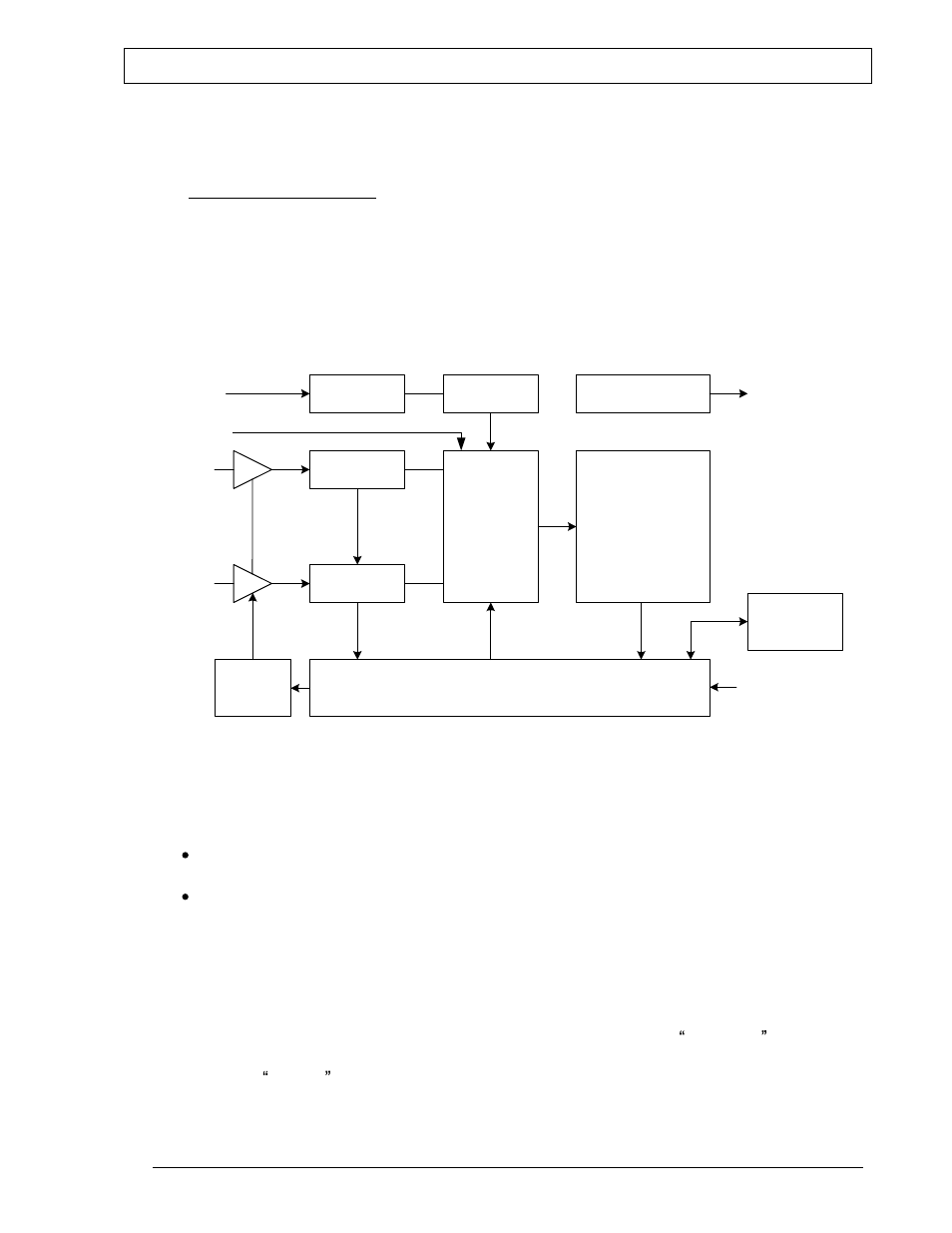
3.1.1. block diagram
Input
control
Timing
controller
Time counter
Interface Controller
155 MHz
Clock
Calibrator
Linear
interpolator
Cal
Ethernet
Linear
interpolator
Clock
converter
10 MHz
Start
Stop
Keyboard
display
Gate
3.1.2. Time interval mode
In timing interval mode the BNC 1120 measures the time between a Start and Stop
pulse. The timing information is obtained by a processing that combines the two following
information:
Coarse information provided by a wide range Time counter running at 155.52 MHz
(6.43 ns resolution),
And fine information provided by the two linear interpolators started by the event
on the Start and Stop inputs.
A gate input can be used to enable or disable all Start and Stop events as desired.
The BNC 1120 can make positive or negative time measurements. The start pulse can
occur before or after the stop pulse.
The number of sequence measurement can be controlled by the sequence command
single/repetitive. In repetitive sequence the number of measurement is controlled by the
value write in sample command.