L.B. White COMBO-MCS User Manual
Page 8
C
Connecting the building controller’s heating contacts to the
SmartBox
™
(for contact closure) for Zone 1 forced air heaters.
(Zone 2 is for radiant heaters and operates independent of
the room controller. This does not require contact closure
wiring)
Connect to the red leads as shown in Fig.11. These are
not powered contacts.
-- Remove the wiring from the heat contacts (one for
each zone) in the room controller.
-- Connect these same contacts to the SmartBox
™
Enable wiring Zone 1, and to common Zone 1.
- This allows each SmartBox
™
zone
to operate within the temperature
parameters of the room controller.
FIG. 11
Wiring from SmartBox
™
to the radiant heaters.
■
The SmartBox
™
operates the variable rate proportional
solenoid control used for the radiant heaters, and
operates independent from the room controller.
■
Separate installation and operation instructions
accompany the appropriate control for manual igntion
or spark ignition radiant heaters.
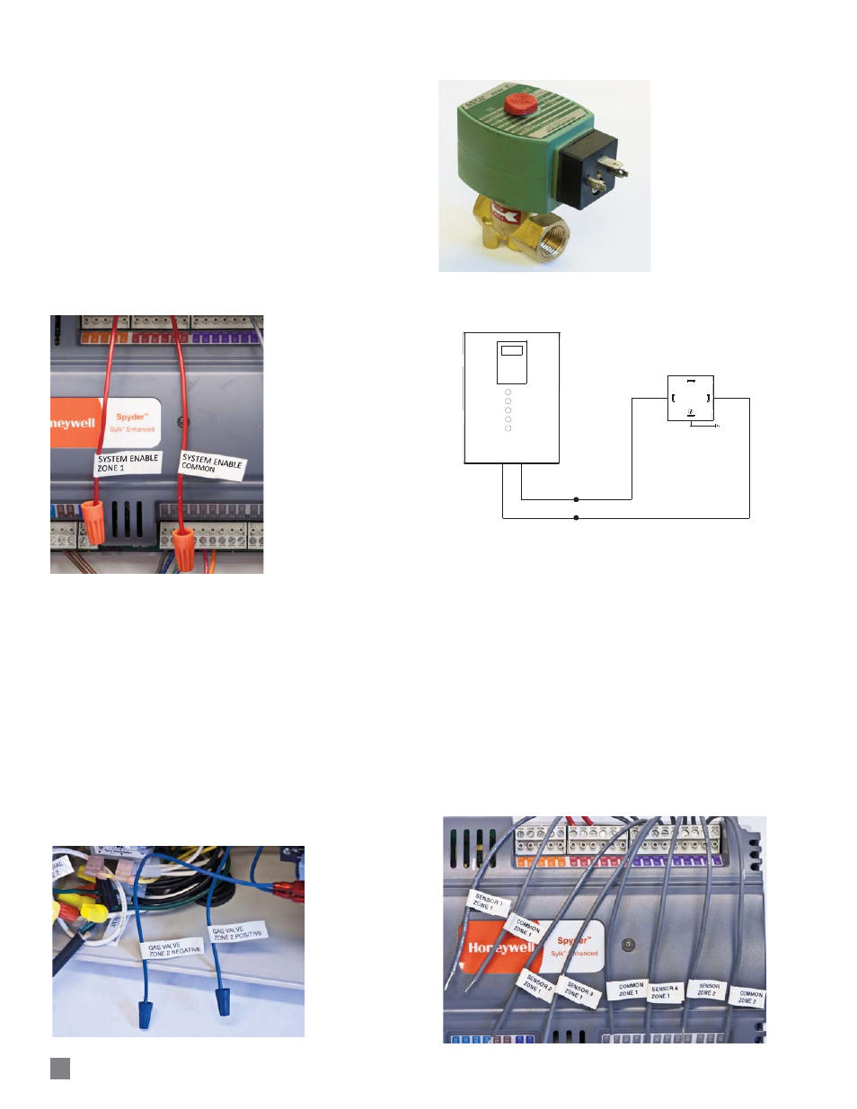
■
See Fig.12 for connection of the SmartBox
™
to the
proportional control valve for radiant heaters. Fig13
identifies the proportional valve and Fig.14 illustrates a
typical connection from the SmartBox
™
to the valve.
FIG. 12
FIG. 13
FIG. 14
Connecting the SmartBox
™
temperature sensors
(Zone 1 has 4 sensors, Zone 2 has 1 sensor)
Connect 18 gauge (minimum) wiring between the gray
leads as shown in Fig.14 and the SmartBox™sensor.
See page 6 for sensor location.
Solder the connection between the SmartBox
™
sensor
and the conductor. Wrap this connection with electrical
tape.
Use only t he L.B.Whit e SmartBox
™
sensors, part
number 572815, provided with the SmartBox
™
, or
order replacements as needed. Do not use sensors
from room controllers as these are not compatible with
the L.B.White SmartBox
™
.
FIG. 14
8
BLUE
BLUE
COMBO SmartBox™
PROPORTIONAL CONTROL VALVE
CONNECTOR BLOCK
+
-
2
1
GROUND