Forced air signal conditioner, Programmable controller – L.B. White COMBO-MCS User Manual
Page 17
This signal conditioners receives 24 VAC from the
lower transformer in the SmartBox
™
, in addition to
a 4-20 mA input signal from the programmable
controller.
The conditioner sends anywhere from 0-15 VDC to
the heater’s variable rate Smar t Sense
™
gas
control for operation, based upon the 4-20 mA
signal supplied from the programmable controller.
See Fig.46 for reference to terminals on the
conditioner when checking voltage and connection
of wiring.
FIG.46
FORCED AIR SIGNAL CONDITIONER
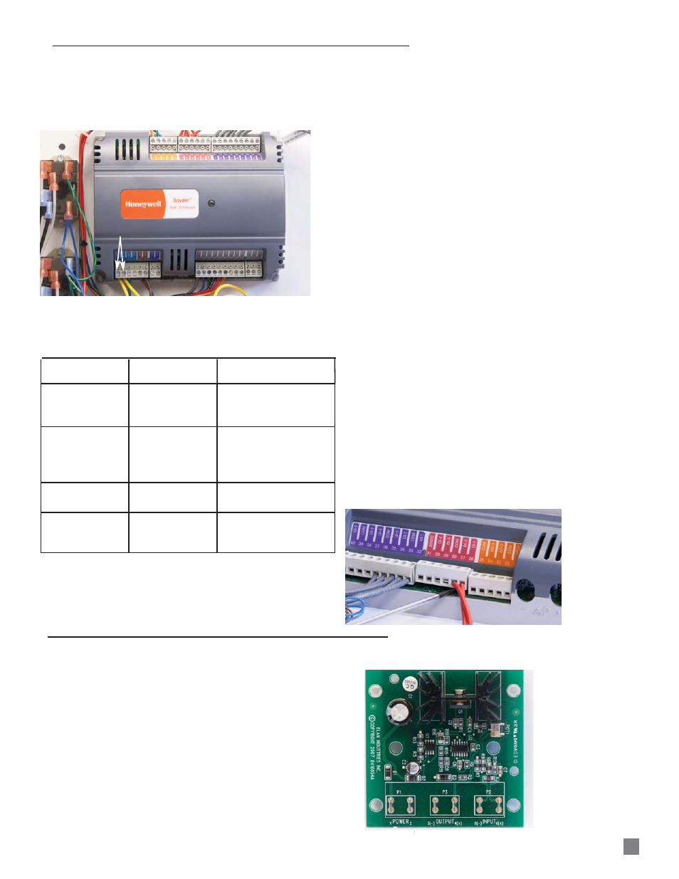
The controller requires 24 VAC for operation which can
be checked at the terminals shown in Fig 44.
(Without 24 VAC, the controller will not operate the
SmartBox
™
)
FIG. 44
The controller also includes an LED which provides
operation status. When power is applied, the LED may
appear in one of the conditions given in the following
table:
:
Replacement
a. Remove all individual wires from the terminal
blocks and reconnect to the replacement
controller
or
b. Remove the terminal blocks with the wiring intact
from original controller and transfer the blocks to
the replacement controller
If transferring the blocks with wiring intact, refer to the
following:
a. Use a thin bladed screw driver to evenly raise the
block from its alignment pins on the replacement
controller.
b. Insert the screwdriver blade no more than 1/8 in. to
prevent damage to the alignment pins.
c. Insert the screwdriver blade at one end of the
terminal block and rotate the blade about 1/4
turn.
d. Move to the other end of the terminal block and
do the same. See Fig.45. Repeat the process until
the block is evenly raised about 1/4 in. from the
alignment pins.
e. Once the block has been elevated, grasp the
block at its center and carefully pull the block
straight up.
f. Complete these same steps for removal of the
blocks with wiring from the original controller.
g. Remove respective blocks from replacement
controller using this process.
h. Transfer the blocks with wiring to the replacement:
-- Position the block onto the respective
alignment pins.
-- Press straight down to firmly seat the
block.
-- Repeat the process for all blocks.
FIG. 45
PROGRAMMABLE CONTROLLER
24 VAC INPUT FROM UPPER TRANSFORMER
LED
17
24 VAC INPUT
FROM LOWER
TRANSFORMER
0-15 VDC OUTPUT
TO GAS CONTROL
4-20 mA INPUT
FROM CONTROLLER
OFF
Not applicable
No power to controller,
low voltage, or controller
damaged
ON
ON steady
Not blinking
Controller is receiving
power but its internal
processor has
malfunctioned.
Very slow blink
(continuous)
1 second ON
1 second OFF
Normal operation
Slow blink
(continuous)
0.5 second ON
0.5 second OFF
Sensor failure
LED
BLINK RATE
STATUS