Relays, Touch pad /display, Transformers – L.B. White COMBO-MCS User Manual
Page 16
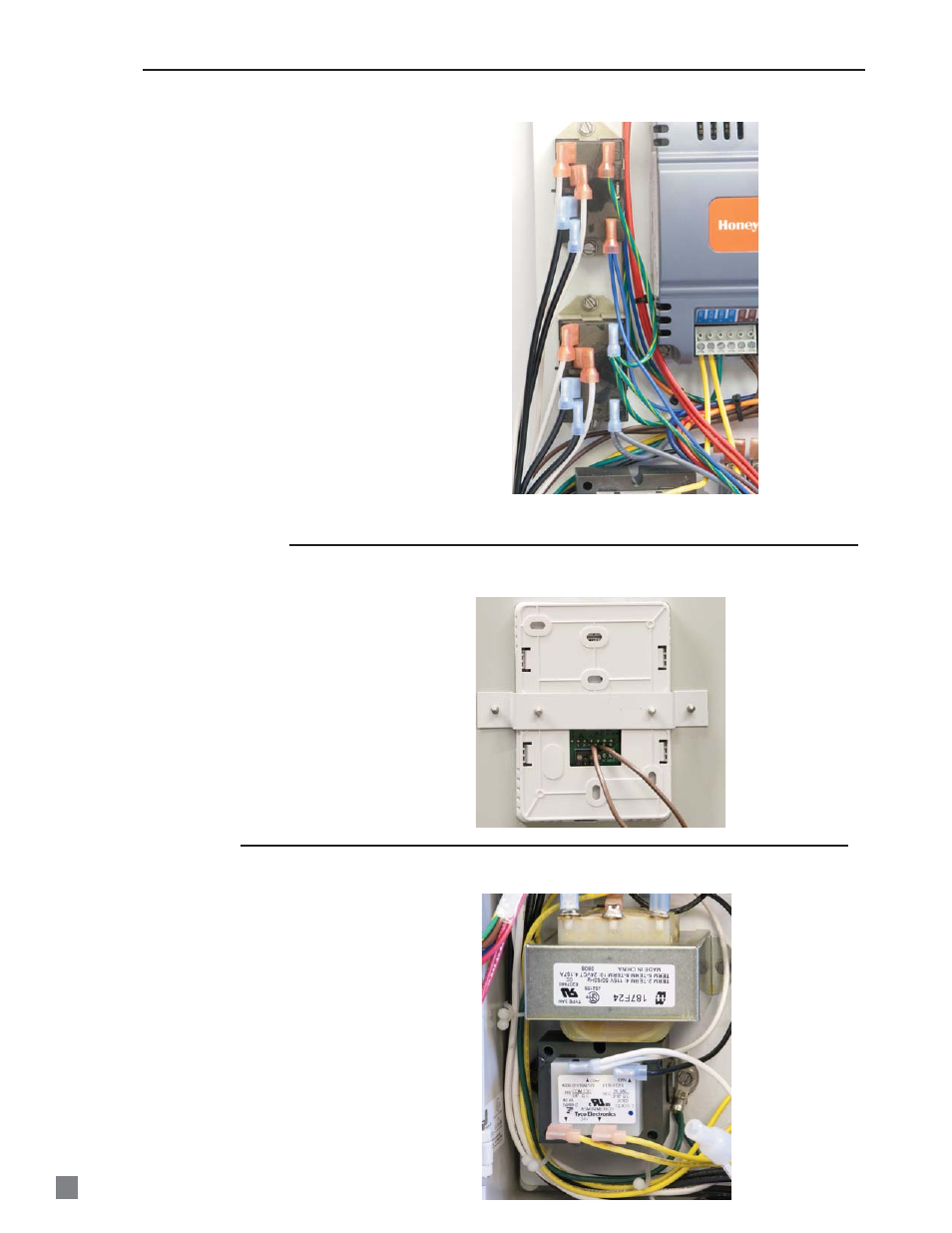
Two relays are mounted in the SmartBox
™
, each
responsible for supplying power to a maximum of
two heaters.
Upper relay: Supplies power to Zone 2 heaters.
Lower relay: Supplies power to Zone 1 heaters.
Refer to Fig. 41 and following table for connection of
wiring and voltage checks.
The relays have numbers adjacent to the male 1/4
in. male connectors for reference.
T
Terminal
Function
2
Power supply neutral
4
Neutral for heater
6
120 VAC power to heater
8
120 VAC power to relay
0
Ground for relay
1
24 VAC input for relay coil
closure (sends 115 VAC from
terminal 8 to terminal 6)
FIG. 41
RELAYS
The touch pad/display allows the user to set up the
SmartBox
™
for system operation, heating days,
temperature, etc.
In the event the pad is being programmed and
erratic displays are observed, or no display, the
display pad must be replaced.
Loosen the small screws securing the brown leads
to the back of the touch pad. See Fig.42.
Remove the sheet metal screws adjacent to the
front of the touch pad.
FIG. 42
TOUCH PAD /DISPLAY
There are two transformers with 120 VAC input
voltages.
Upper transfomer- 24 VAC to the programmable
c o n t ro l l e r a n d to t h e r a d i a n t h e a te r s i g n a l
conditioner.
Lower transformer- 24 VAC output to the forced air
signal conditioner for use in operating the variable
rate gas control valves.
Both transformers must supply 24VAC for complete
system operation.
FIG. 43
TRANSFORMERS
LOWER TRANSFORMER
UPPER TRANSFORMER
2
4
6
8
0
1
ZONE 2 RELAY
ZONE 1 RELAY
2
4
6
8
0
1
16