Interconnection – L.B. White COMBO-MCS User Manual
Page 7
■
A
All wiring must be done by a qualified electrician in
accordance with local, state, and national electrical
codes.
■
Unlatch the control box cover, and open the control
panel.
■
Select locations on either the side or the bottom where
a wiring access holes may be drilled. Do not drill holes
at the top of the control box.
■
Install the appropriate sized water tight connectors.
■
Use customer supplied minimum 18 gauge conductor
and the appropriate wiring terminals for connecting the
Smart Box
™
to the heater’s variable gas control valve,
to the room controller contacts, and the temperature
sensors.
■
Re fe r to t h e fo l l ow i n g i n s t r u c t i o n s fo r w i r i n g
c o n n e c t i o n s . Re fe r to t h e w h i te f l a g s o n t h e
SmartBox
™
leads for interconnections.
Connecting the 120 VAC Power Supply to the SmartBox
™
.
Connect to hot, neutral, and ground leads as shown in
Fig.6.
FIG. 6
Connecting 120 VAC Power to the Heaters
Connect leads in SmartBox
™
to heating Zones 1 and 2.
See Fig.7.
FIG. 7
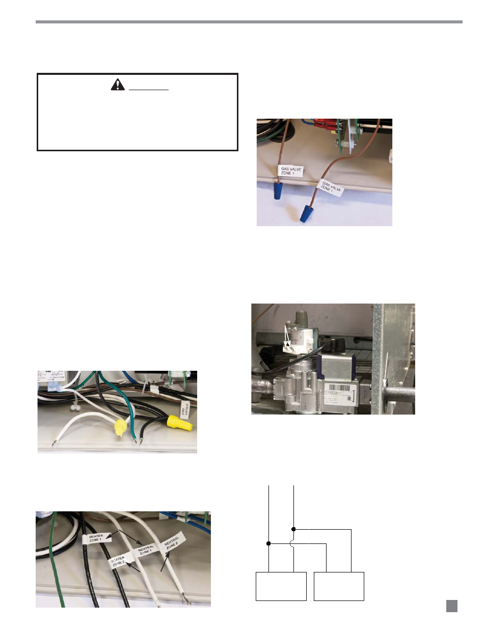
Wiring from SmartBox
™
to the forced air heater’s Smart
Sense
™
variable rate gas control valve
a. Connect the Smart Sense™ gas control valve wiring
for Zone 1 at the brown SmartBox
™
leads as
shown in Fig.8.
FIG. 8
b. Route the wiring from these leads through the
gas inlet hole at the heater’s case. See Fig.9.
c. Attach 1/4 in. insulated female terminals to
these wires and connect to either terminal on
the valve. See Fig. 9.
FIG. 9
d.
See Fig.10 for typical connections. Each SmartBox
™
zone can control two heaters.
FIG. 10
7
Interconnection
ROUTE WIRING
THROUGH HOLE
CONNECT WIRING TO TERMINALS
( NOT POLARITY SENSITIVE)
WARNING
Electrical Shock Hazard
■
Disconnect the electrical supply before installation of
the SmartBox
™
.
■
Failure to follow this warning may result in personal
injury or death.
USED FOR SPARK IGNITION
RADIANT HEATERS ONLY. DO
NOT USE FOR MANUAL IGNITION
RADIANT HEATERS
FORCED AIR
WIRING FROM
Smart Box™
To FORCED AIR
Smart Sense™
VARIABLE RATE GAS CONTROL VALVE
VOL
TS T
O V
AL
VE
VA
LV
E
HEATER 1
GAS VALVE
HEATER 2
GAS VALVE