Sensor location, Fig. 5 – L.B. White COMBO-MCS User Manual
Page 6
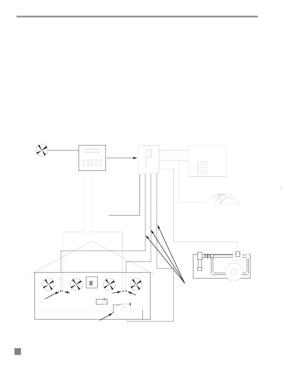
Sensor Location
Each SmartBox
™
controls two zones of heat.:
-- Zone 1: Two forced air heaters
One SmartBox
™
sensor may be used for each zone of
heat. However two or more sensors are used for
optimum temperature management.
-- Zone 2: Radiant heaters
Use only the L.B.White SmartBox
™
sensors provided
with the SmartBox
™
, or order replacements as
needed. Do not use sensors from other controller
s ys t ems a s t hese a re not com p a ti b l e wi th t he
L.B.White SmartBox
™
.
See below for proper SmartBox
™
sensor location.
6
GUARDIAN
w/ SMARTSENSE™
ZONE1
ZONE2
CYCLE
SENSOR
RESET
ROOM CONTROLLER
FAN(S)
SmartBox™ SYSTEM DIAGRAM
FORCED AIR AND RADIANT HEATERS
SmartBox
™
GUARDIAN WITH
Smart Sense™
120 VAC
POWER SUPPLY
120 VAC
POWER SUPPLY
120 VAC TO SPARK IGNITION
INFRACONICS ONLY (ZONE 2)
CONTROL SIGNAL TO ZONE PANEL VARIABLE RATE
SOLENOID VALVE (USE MINIMUM 18 GAUGE WIRING))
GUARDIAN WITH
Smart Sense™
ENABLE
USE 18 GAUGE WIRE FROM THE
SmartBox™TO EACH TEMPERATURE SENSOR
LOCATION. UP TO 4-FORCED AIR AND
1 RADIANT ZONE
RADIANT SENSOR
ZONE PANEL
ROOM CONTROL SENSORS
SmartBox™ SENSOR(S) LOCATED WITHIN 6 IN. OF
EXISTING ROOM SENSOR AND AT SAME HEIGHT
SmartBox™ SENSOR(S) LOCATED WITHIN 6 IN. OF
EXISTING ROOM SENSOR AND AT SAME HEIGHT
FIG. 5