Leveling the table, Installing the foot control, Installing the upholstery – Brewer Assist Power User Manual
Page 6: Installation (continued)
Document # 99300 RevA
6
Printed in USA © 2008
Leveling the Table
A leveling screw pad (Figure 5) is located in six places
under the table’s base. Adjust the six leveling pads to
achieve a solid, level installation.
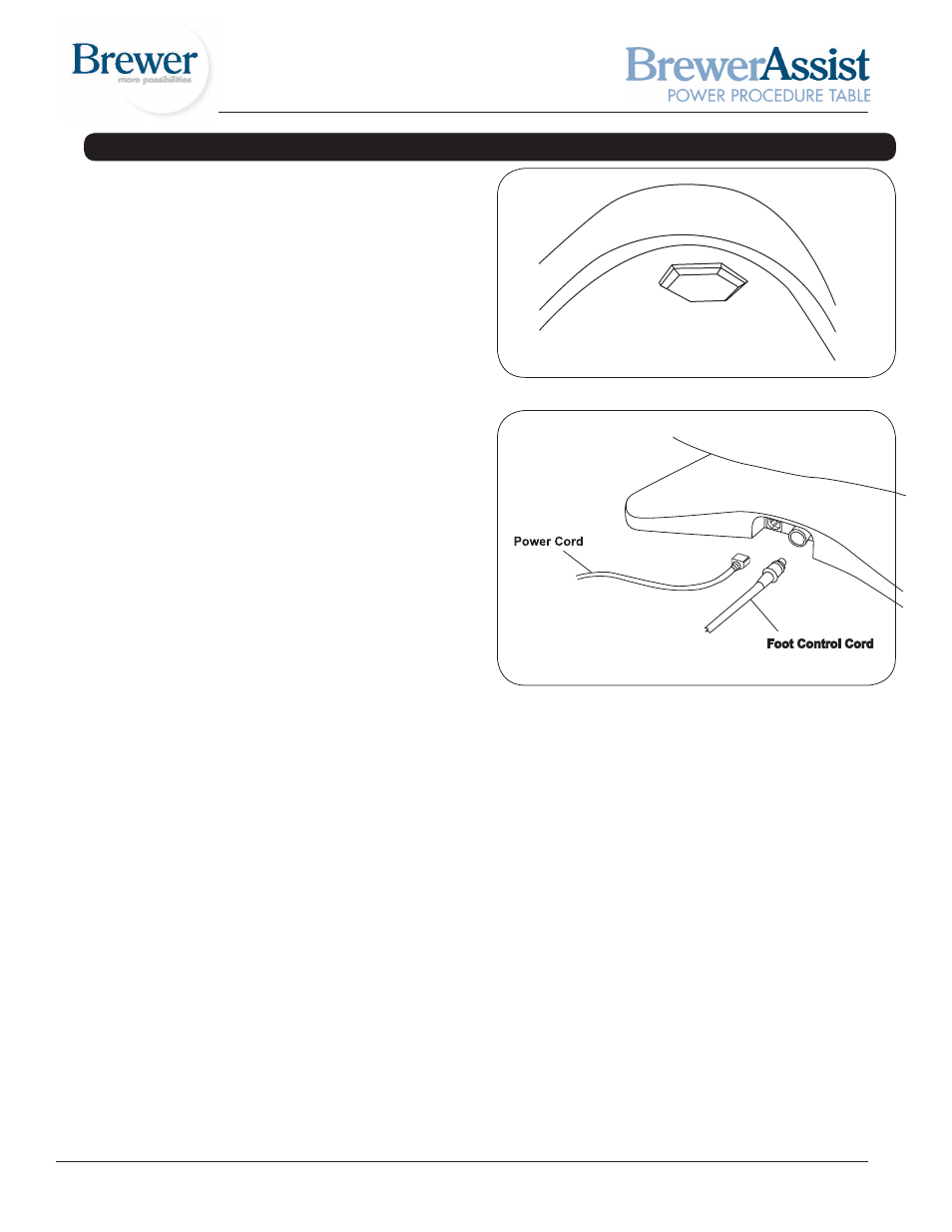
Installing the Foot Control
1. Remove the foot control from the shipping box.
2. Insert the end of the cord into the foot control recep-
tacle on the table (Figure 6). Make sure the tab in the
cord receptacle is pointing upward and receptacle is
fully seated. Test the foot control for operation.
Installing the Upholstery
The upholstery set includes: Headrest shroud and cush-
ion, Seat/Back cushion, and Legrest cushion.
H
eadrest
s
Hroud
and
C
usHion
1. Raise the back so the top of the headrest is at a com-
fortable work height.
2. Align the holes in the headrest cushion, shroud, and
headrest mounting link. Make sure cushion is prop-
erly centered on the shroud. Fasten with the four
screws provided.
s
eat
/B
aCk
C
usHion
1. Refer to the Operation section in this manual and
position the table so the seat, back and legrest are
flat (in the horizontal position). (Figure 7)
2. Place the seat/back cushion on the table with the
curved end toward the headrest and the straight end
facing the legrest (Figure 8). Adjust the cushion so
that the straight end overhangs the seat frame by ap-
proximately 4”.
3. Push down lightly in the middle of the cushion and
shift it toward the headrest until the 4 posts on the
bottom side of the cushion drop into the 4 slots in
the seat frame. Pull up slightly on the middle of the
cushion to make sure the posts have engaged with
the slots.
4. Align the two threaded holes on the headrest end of
the cushion with the two holes in the frame. Attach
with two screws provided.
5. Align the two threaded holes on the legrest end of the
cushion with the two holes in the frame. Attach with
two screws provided.
Figure 5. Leveling Screw Pad (located under table)
Figure 6. Power Cord & Foot Control Cord Receptacles
INSTALLATION (CONTINUED)
L
egrest
C
usHion
1. Position legrest in the horizontal position. Raise the
table to it’s fullest height.
2. Align the holes in the legrest cushion and legrest
plate, then fasten with the four screws provided.