3 back panel, 4 the effect algorithms – Behringer DSP1200P User Manual
Page 11
11
E
The MODULIZER PRO enters Mix mode. When the display reads two dashes, the DSP1200P is
in External Mix mode, and when a figure is read, Internal Mix mode is selected. To toggle
between the two modes, simply press both EQ keys for about 1 second.
In Internal Mix mode you can use the jog wheel to freely select the effect intensity in each preset within a range
from 0% to 100%, a highly useful feature, for instance, to insert the DSP1200P in the effect loop of a guitar
amp. Good results can be achieved with settings between 20% and 50%.
Another key combination can be used to enter MIDI mode. With the MODULIZER PRO switched on, proceed
as follows:
s
Press and hold the keys IN/OUT and STORE for about two seconds, the DSP1200P automati-
cally enters MIDI mode. Use the IN/OUT key to step through the various MIDI parameters. Press
any other key to quit MIDI mode.
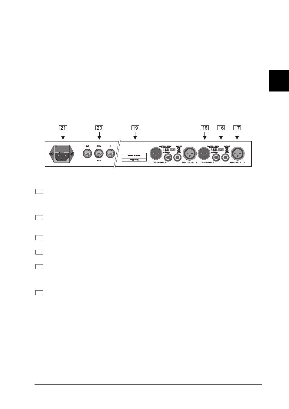
1.3.3 Back panel
Fig. 1.4: Back panel connectors and control elements
16
Use the OPERATING LEVEL switch to adapt the MODULIZER PRO to different operating levels. You
can select a -10 dBV semi-pro level used for home recording and a +4 dBu level used in professional
studios. The level indicators on the front panel are automatically adapted to read the selected nominal
level, i.e. an optimum operating range of the meters is always guaranteed.
17
These are the MODULIZER PROs analog INPUTS. The MODULIZER PRO has both XLR and jack
inputs and outputs. Each XLR and jack set are wired parallel and can be used either balanced and
unbalanced.
18
These are the MODULIZER PROs analog OUTPUTS. Also on balanced or unbalanced XLR or TRS
jacks.
19
These are the MODULIZER PROs MIDI connectors (MIDI OUT / THROUGH / IN). Via these connectors
total remote control is possible.
20
Please take the time to make shure that the SERIAL NUMBER is printed correctly in the space provided
on the enclosed Warranty Registration Card. Put the instruction manual in a safe place and return the
completed Warranty Registration Card to us within 14 days of purchase, making sure that the dealer
stamp has been acquired.
21
This is the MAINS CONNECTOR / FUSE HOLDER / VOLTAGE SELECTOR. Before you connect the
unit, please make sure that the displayed voltage corresponds to your Mains supply. Please note that
the AC voltage selection is defined by the position of the Fuse Holder. If you intend to change the
operating voltage, remove the Fuse Holder and turn it by 180 degrees before you reinsert it. Matching the
two markers monitors the selected voltage. Please note that, depending on the mains voltage supplied
to the unit, the correct fuse type and rate must be installed (see chapter 6.5 SPECIFICATIONS).
Please use the enclosed mains cable to connect the unit to the mains power supply.
+
Please note that not all appliances can be used with different mains voltage ratings. Please
check the description on the back of the unit and the box.
1. INTRODUCTION