Instruction manual – model cf1400 oil burner, Burner fuel flow – Beckett CF 1400 User Manual
Page 9
9
Form 6104 BCF14N-R0299
Instruction Manual – Model CF1400 Oil Burner
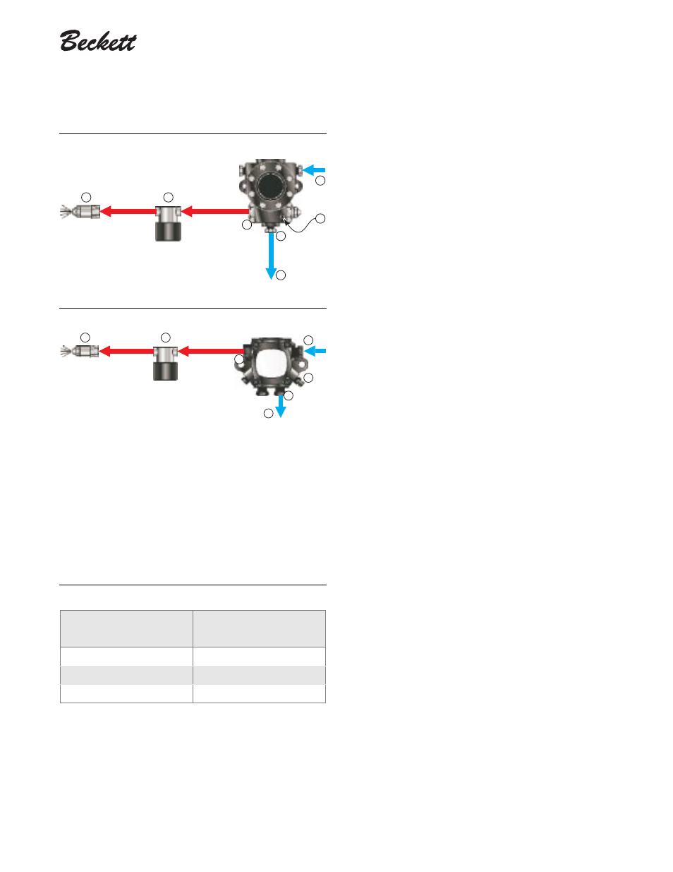
Figure 9a – Two-pipe oil flow with “H” pump
300 psig
k
g
1413ao
d
a
b
p
300 psig
c
Figure 9b – Two-pipe oil flow with “B” pump
d
b
g
p
300 psig
300 psig
c
1423ao
a
k
a Return port
b Nozzle port
c Oil valve
d Nozzle & adapter
Legend
g Inlet port
k Return line to oil tank
p Air bleed valve
Table 3 – Fuel unit gearset capacities
Fuel unit
model number
Gearset capacity
(gallons per hour)
B2TA8245
21
H3PAN-C150H
61
H4PAN-C151H
69
for the fuel unit gearset capacity - the rate at which fuel is
recirculated when connected to a two-pipe system. Size
two-pipe oil lines based on this flow rate.
• Use continuous lengths of heavy-wall copper tubing,
routed under the floor where possible. Do not attach fuel
lines to the appliance or to floor joists if possible. This will
reduce vibration and noise transmission problems.
• Install an oil filter sized to handle the fuel unit gearset flow
capacity (
Table 3
) for
two-pipe systems
. Size the filter
for the firing rate for
one-pipe systems
. Locate the filter
immediately adjacent to the burner fuel unit.
• Install two high-quality shut-off valves in accessible loca-
tions on the oil supply line. Locate one valve close to the
tank. Locate the other valve close to the burner, upstream
of the fuel filter.
❏ Burner fuel flow
•
One-pipe systems
– See
Figure 8
for the fuel flow path.
•
Figure 8a
is based on type
H
fuel units.
•
Figure 8b
is based on type
B
fuel units.
• Oil supply connects to one of the fuel unit inlet ports.
•
Two-pipe systems
– See
Figure 9
for the fuel flow paths
for two-pipe oil systems.
•
Figure 9a
is based on type
H
fuel units.
•
Figure 9b
is based on type
B
fuel units.
• Oil supply connects to one of the fuel unit inlet ports.
Oil return connects to the fuel unit return port. (
Install
the by-pass plug in the fuel unit for two-pipe sys-
tems.
)
•
Nozzle pressure
– The fuel unit nozzle port pressure is
factory set at 300 psig. Some original equipment manufac-
turer burner applications may call for a lower pressure to
obtain a required firing rate. Do not change this pressure
unless directed to do so by the appliance manufacturer.