Liebherr LTM 1500-8.1 User Manual
Page 12
12
LTM 1500-8.1
Legend
LSB Liebherr system bus 1
LSB Liebherr system bus 2
LSB Liebherr system bus 3
LSB Liebherr system bus 4
LSB Liebherr system bus 5 (also for TN mode)
LSB Liebherr system bus 6 (also for TA mode)
CAN busse
SCI serielle communication interface
1 Input/output modules for electronic control of suspension,
Liebherr Diesel engine, automatic transmission, operating
functions, compressed air control for brake function
1a Instruments-key board unit in driver’s cabin
2
Input/output module for differential locks, display functions
3
Input/output module for outriggers - right
3a Control unit for outriggers - right
4
Input/output module for outriggers - left
4a Control unit for outriggers - left
5
Input/output module for engine brake, tempostat, temposet,
electronic control of Diesel engine (steering column switch,
right) and automatic transmission
6
Control of Allison automatic transmission
7
Control of injection pump Liebherr Diesel engine/carrier
8 Slewing sensor slipring unit
9 Connection Liebherr system bus (LSB 1, 2, 3, 4, 5, 6)
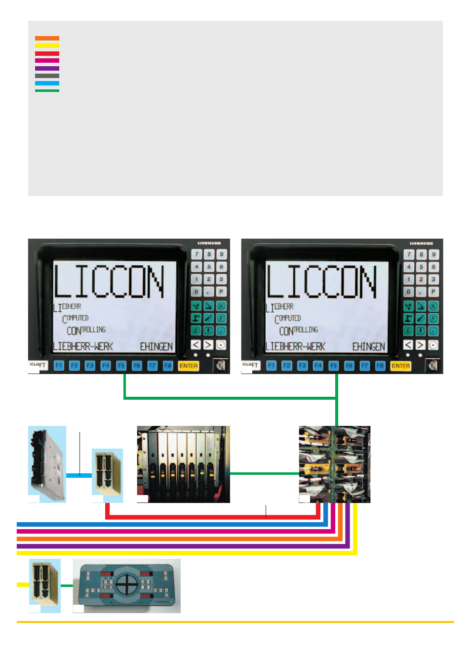
10 LICCON central unit
11 LICCON monitors in the crane cabin
12 Length sensor
13 Cable drum/energy cable for interlocking gripper/telescopic
boom
14 Inductive sensors (12 x)
15 Angle sensor on the base section
16 Cable drum for items 17, 18, 19 and jib
17 Wind sensor
18 Hoist limit switch
19 Angle sensor
20 Input/output module for electronic control of Diesel
engine/superstructure, air flap, ventilator clutch,
exhaust flap
21 Control of injection pump Liebherr Diesel
engine/superstructure
LSB 3
CAN-Bus
4a
4
9
10
20
21
11
11