Bryant COMMERCIAL AIR COOLED CONDENSING UNITS 576b User Manual
Page 11
—
11
—
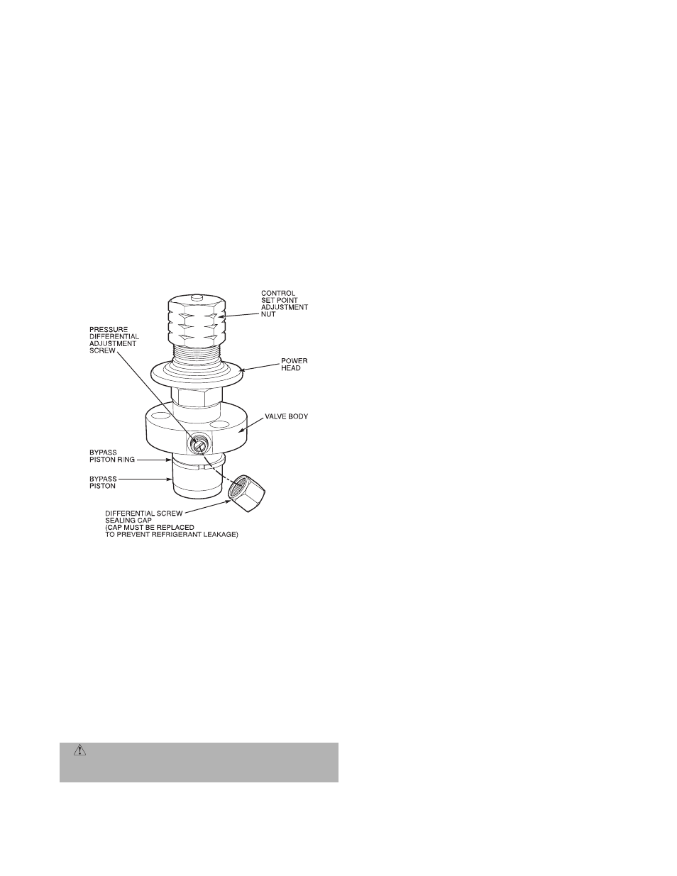
IV. CAPACITY CONTROL (576B120 Only)
A suction pressure-actuated unloader controls 2 cylinders
and provides capacity control. Unloaders are factory set (see
Table 1), but may be field adjusted:
A. Control Set Point
The control set point (cylinder load point) is adjustable from
0 to 85 psig. To adjust, turn control set point adjustment nut
(Fig. 12) clockwise to its bottom stop. In this position, set
point is 85 psig. Then, turn adjustment counterclockwise to
desired control set point. Every full turn counterclockwise
decreases set point by 7.5 psig.
B. Pressure Differential
The pressure differential (difference between cylinder load
and unload points) is adjustable from 6 to 22 psig. To adjust,
turn pressure differential adjustment screw (Fig. 12) coun-
terclockwise to its back stop position. In this position, differ-
ential is 6 psig. Then, turn adjustment screw clockwise to
desired pressure differential. Every full turn clockwise
increases differential by 1.5 psig.
V. COMPRESSOR REMOVAL
See Table 1 for compressor information.
Follow safety codes and wear safety glasses and work gloves.
1. Shut off power to unit and install lockout. Remove
unit access panel (front of unit).
2. Remove refrigerant from system using refrigerant
removal methods described in GTAC II, Module 5,
Charging, Recovery, Recycling, and Reclamation.
3. Disconnect compressor wiring at compressor termi-
nal box.
4. Remove bolts from suction flange and discharge ser-
vice valve (576B units).
5. Remove crankcase heater from compressor base
(576B units only).
6. Remove compressor holddown bolts.
7. Remove compressor from unit.
8. Clean system. Add new liquid line filter drier.
9. Install new compressor in unit.
10. Connect suction and discharge lines to compressor.
Ensure that compressor holddown bolts are in place.
11. Install crankcase heater.
12. Connect wiring.
13. Evacuate and recharge unit, per Step VII.
14. Restore unit power.
VI. CRANKCASE HEATER
The crankcase heater prevents refrigerant migration and
compressor oil dilution during shutdown when compressor is
not operating.
Close both compressor service valves if applicable when
crankcase heater is deenergized for more than 6 hours.
VII. REFRIGERANT CHARGE
Unit panels must be in place when unit is operating during
charging procedure. Unit is shipped with a holding charge
only. Weigh in 7 lbs of R-22 to start unit. Refer to GTAC II,
Module 5, Charging, Recovery, Recycling, and Reclamation
for additional information.
See Troubleshooting Guide on page 13 for additional
information.
A. Low Charge Cooling
Using Cooling Charging Charts, Fig. 13 and 14, vary refrig-
erant until the conditions of the appropriate chart are met.
Note the charging charts are different from type normally
used. The charts are based on charging the units to the cor-
rect sub-cooling for the various operating conditions. Accu-
rate pressure gage and temperature sensing device are
required.
Connect the pressure gage to the service port on the liquid
line service valve. Mount the temperature sensing device on
the liquid line, close the liquid line service valve, and insu-
late it so that outdoor ambient temperature does not affect
the reading. Indoor-air cfm must be within the normal oper-
ating range of the unit.
Operate unit a minimum of 15 minutes. Ensure that temper-
ature and pressure have stabilized. Plot liquid pressure and
temperature on chart and add or reduce charge as required.
Do not vent refrigerant to the atmosphere. Recover any
excess charge. Operate the unit until the system stabilizes.
Adjust charge to conform with charging chart, using liquid
pressure and temperature to read chart.
B. Refrigerant Leaks
Proceed as follows to repair a refrigerant leak and to charge
the unit:
1. Locate the leak and ensure that refrigerant system
pressure has been relieved.
2. Repair leak following accepted practices.
NOTE: Install a new filter drier in the liquid line whenever
the system has been opened for repair.
3. Add a small charge of R-22 refrigerant vapor to sys-
tem and leak-test unit.
4. Evacuate refrigerant system up to 500 micons. If
additional leaks are not found.
5. Charge unit with R-22 refrigerant.
NOTE: Do not vent refrigerant to the atmosphere. Recover
any excess charge.
CAUTION: Excessive movement of copper lines at
compressor may cause higher levels of vibration when
unit is restored to service.
Fig. 12 — Compressor Capacity Control Unloader