2 configuration test label – Brady 2034 User Manual
Page 42
_______________________________________________________________________
36
Using Your Printer
3.3.2 Configuration Test Label
The following are explanations of the Configuration Test Label elements,
top to bottom, (see Figure 3-5).
Rom Checksums
−
indicates whether the ROMs that store the Printer's
program and resident fonts are 'good' or 'bad'. Good part numbers are
displayed normally. Checksum values replace the part numbers to indicate
an error. If either the ROM or RAM test is bad, service is required.
System Ram Checks
−−
indicates 'good' or 'bad'.
System Ram Size
−
indicates the amount of available RAM in the Printer.
Thermal Transfer Switch
−
Should be 'on' if using a ribbon, and 'off ' if
in the direct-thermal mode (no ribbon).
Switch 1
−
indicates the status of dip switch 1 on the rear of the printer,
(see Section 2.3.2, Table 2-3).
Internal
−
indicates the status of the Printer's internal dip switch located
on the main logic board (see Table 3-1).
Paper
−
this value indicates when paper is present in the sensor.
Edge and Refl
−
indicates when media is present at the respective sensor.
These sensors tell the Printer where the start of the label is located. Refer
to the Programmer's Manual when determining which sensing mode to
use.
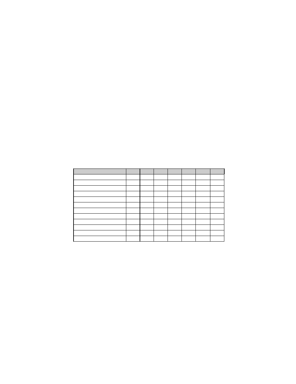
Switch Functions
1
2
3
4
5
6
7
RS-422 Disabled
OFF
OFF
OFF
X
X
X
X
RS-422 Address 1
ON
OFF
OFF
X
X
X
X
RS-422 Address 2
OFF
ON
OFF
X
X
X
X
RS-422 Address 3
ON
ON
OFF
X
X
X
X
RS-422 Address 4
OFF
OFF
ON
X
X
X
X
RS-422 Address 5
ON
OFF
ON
X
X
X
X
RS-422 Address 6
OFF
ON
ON
X
X
X
X
RS-422 Address 7
ON
ON
ON
X
X
X
X
Spare
X
X
X
OFF
X
X
X
Resettable Counter Reset
X
X
X
X
OFF
X
X
Spare
X
X
X
X
X
OFF
X
RS-422 Termination (hw)
X
X
X
X
X
X
OFF
Table 3-1 Internal Dip Switch Settings