B&B Electronics 3PCIU4 User Manual
Page 83
Connector
Pinouts
Manual Documentation Number 3PCIoUx-1008
Appendix B
B -1
A
A
p
p
p
p
e
e
n
n
d
d
i
i
x
x
B
B
:
:
C
C
O
O
N
N
N
N
E
E
C
C
T
T
O
O
R
R
P
P
I
I
N
N
O
O
U
U
T
T
S
S
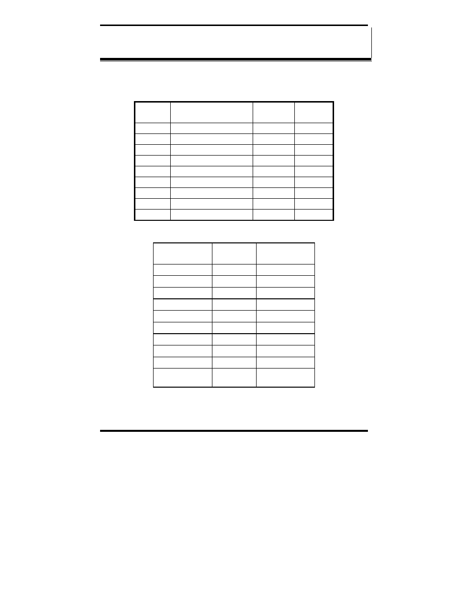
RS-232 Pinouts
Name Description Direction
(DTE)
DB-9M
Pin
DCD
Data Carrier Detect
Input
1
RD Receive
Data Input
2
TD Transmit
Data Output
3
DTR Data
Terminal
Ready Output 4
GND Signal
Ground ------ 5
DSR
Data Set Ready
Input
6
RTS Request
to
Send Output 7
CTS
Clear to Send
Input
8
RI Ring
Indicator Input
9
Figure 56. RS-232 Signal Designations and DB-9 Pinout
Signal Name
DB-9 Pin
(DTE)
DB-25 Pin
(DTE)
DCD 1 8
RD 2 3
TD 3 2
DTR 4 20
GND 5 7
DSR 6 6
RTS 7 4
CTS 8 5
RI 9 22
Chassis GND
Shield (DB-
9 Shell)
1
Figure 57. RS-232 DB-9 to DB-25 Conversion Cable Pinout