B&B Electronics 3PCIU4 User Manual
Page 65
RS-422/ 485 Connections/Operation
Manual Documentation Number 3PCIoUx-1008
Chapter 8
59
C
C
h
h
a
a
p
p
t
t
e
e
r
r
8
8
:
:
R
R
S
S
-
-
4
4
2
2
2
2
/
/
4
4
8
8
5
5
C
C
o
o
n
n
n
n
e
e
c
c
t
t
i
i
o
o
n
n
s
s
/
/
O
O
p
p
e
e
r
r
a
a
t
t
i
i
o
o
n
n
RS-422/485 Mode
In RS-422/RS-485 mode MIport serial ports provide two sets of differential
signal pairs and signal ground for each port. The RS-422 and RS-485
standards use balanced differential drivers and receivers for each signal. This
facilitates greater communication distances than unbalanced systems such as
RS-232.
RS-422 operation is suitable for interconnecting a computer and one device
for full duplex (point-to-point) bi-directional communication, or a computer
and several devices for unidirectional (point-to-multipoint) communication.
RS-422 interfaces are commonly used for video editing/control, camera
control, electronic signage, television studio/satellite dish control,
performance lighting and audio equipment control.
RS-485 operates with the same signals and signal levels as RS-422 but differs
in that it allows multiple devices to share the same communication link using
half duplex (2-wire) or full duplex (4-wire) connections. RS-485 interfaces
are commonly used in manufacturing and industrial/commercial control
applications such as programmable logic controllers, telemetry, and process
control.
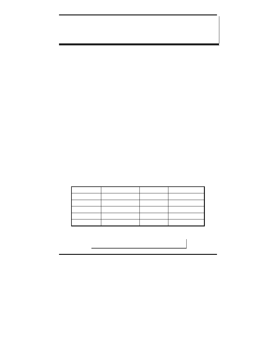
RS-422/485 Signal Designations and DB-9 Pinout
Name
Description
Direction
DB-9 M Pin
RD(A)
−
Receive Data A
Input
1
TD(B) +
Transmit Data B
Output
2
TD(A)
−
Transmit Data A
Output
3
GND Signal
Ground ------
5
RD(B) +
Receive Data B
Input
9
Figure 43. RS-422/485 Signal Designations and DB-9 Pinout
Note: Refer to Appendix B for additional cable configurations and
pinouts